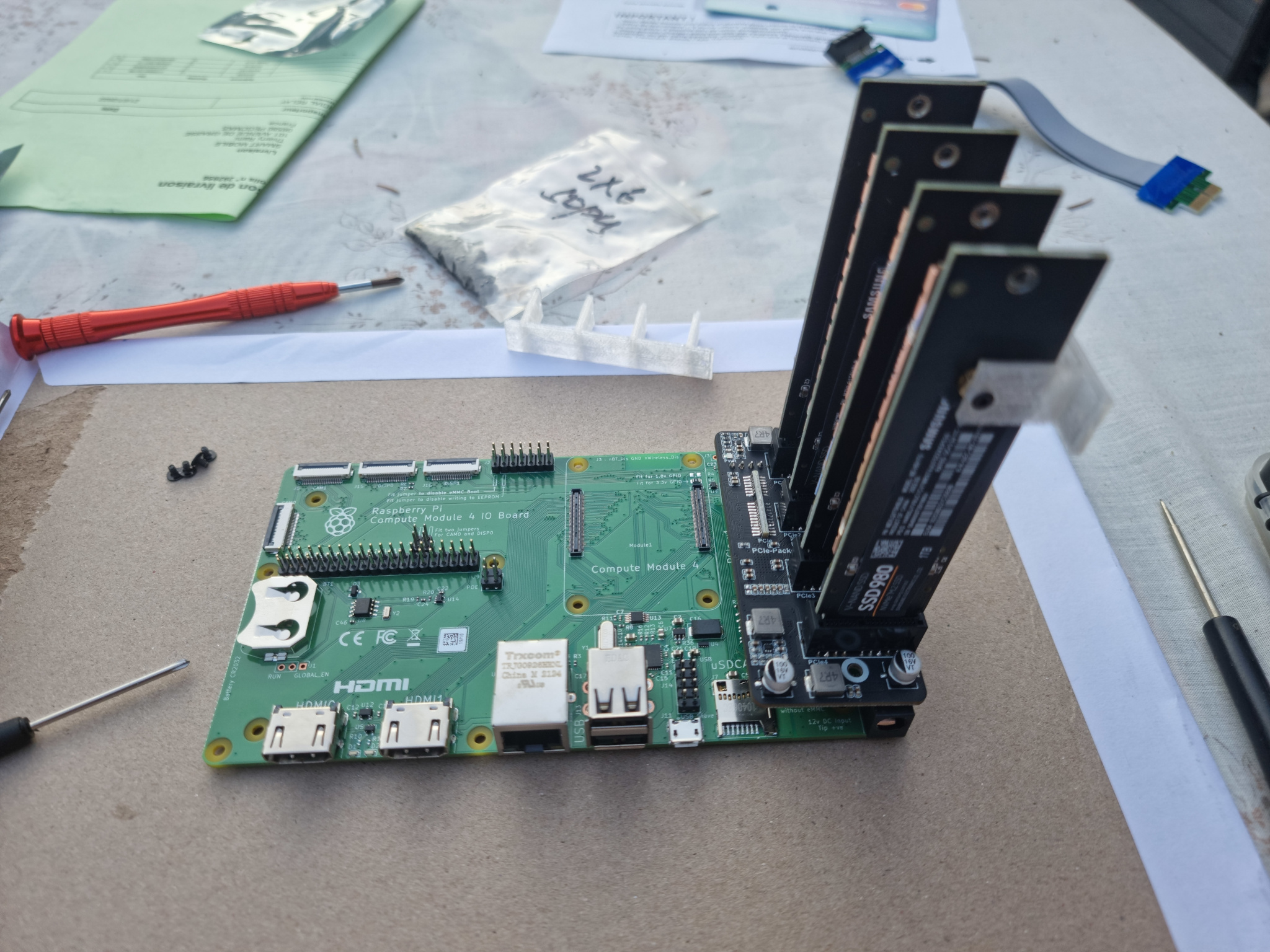
But faire un NAS :
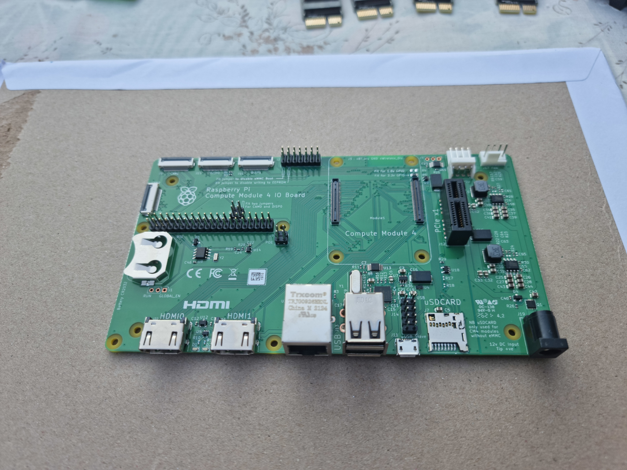
Partie matérielle : avec la carte Raspberry Pi Compute Module 4 IO Board , une carte CM4 , une carte extension Pci-e vers 4xpci-e , et quattre disque nvme de 1To ( avec adaptateur nvme / Pci-e )
Partie Logicielle : surement avec openmediavault , ou autre pas encode décidé /
carte Raspberry Pi Compute Module 4 IO Board
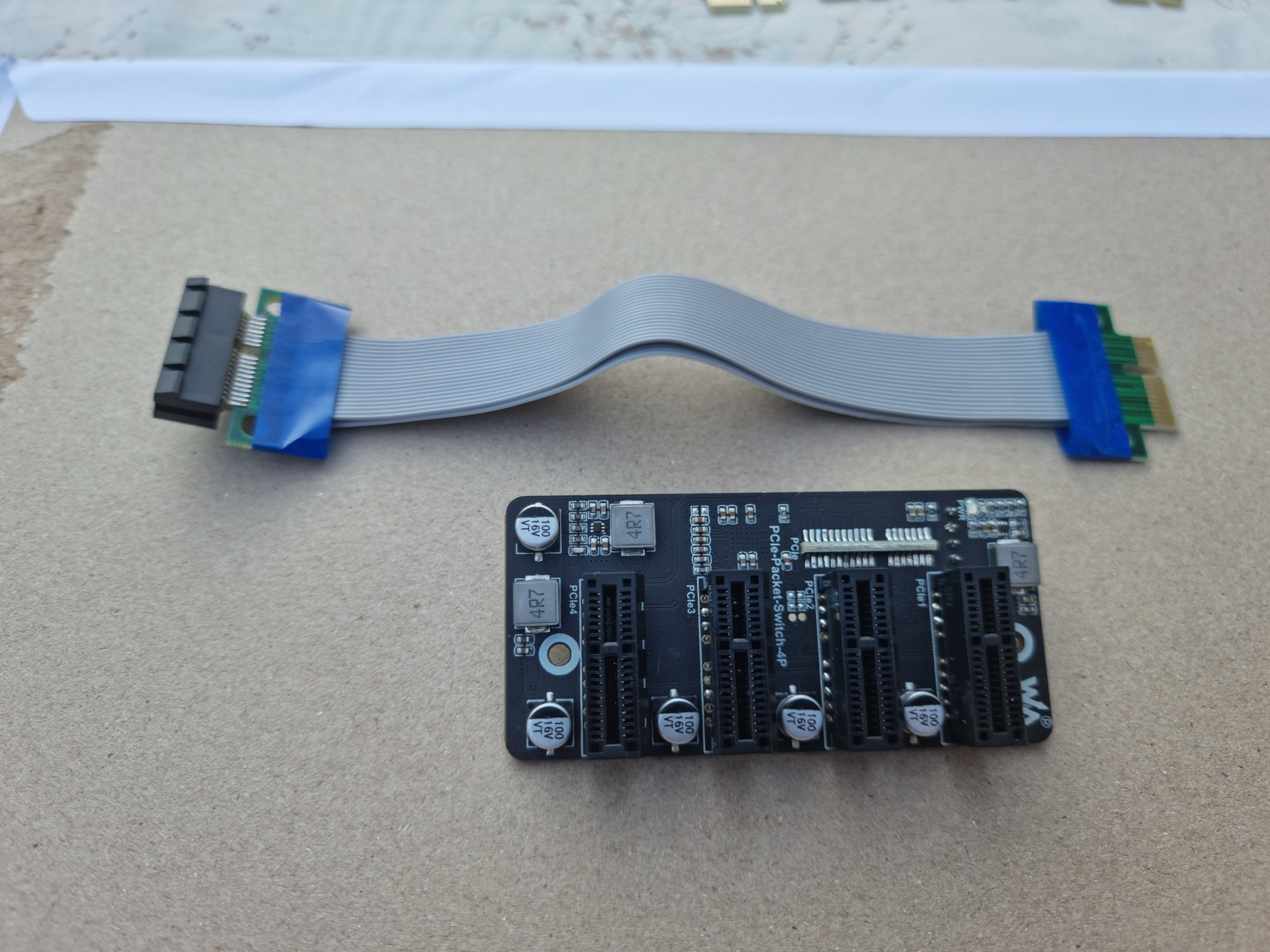
La carte d’extension PCI-e vers 4 x PCI-e
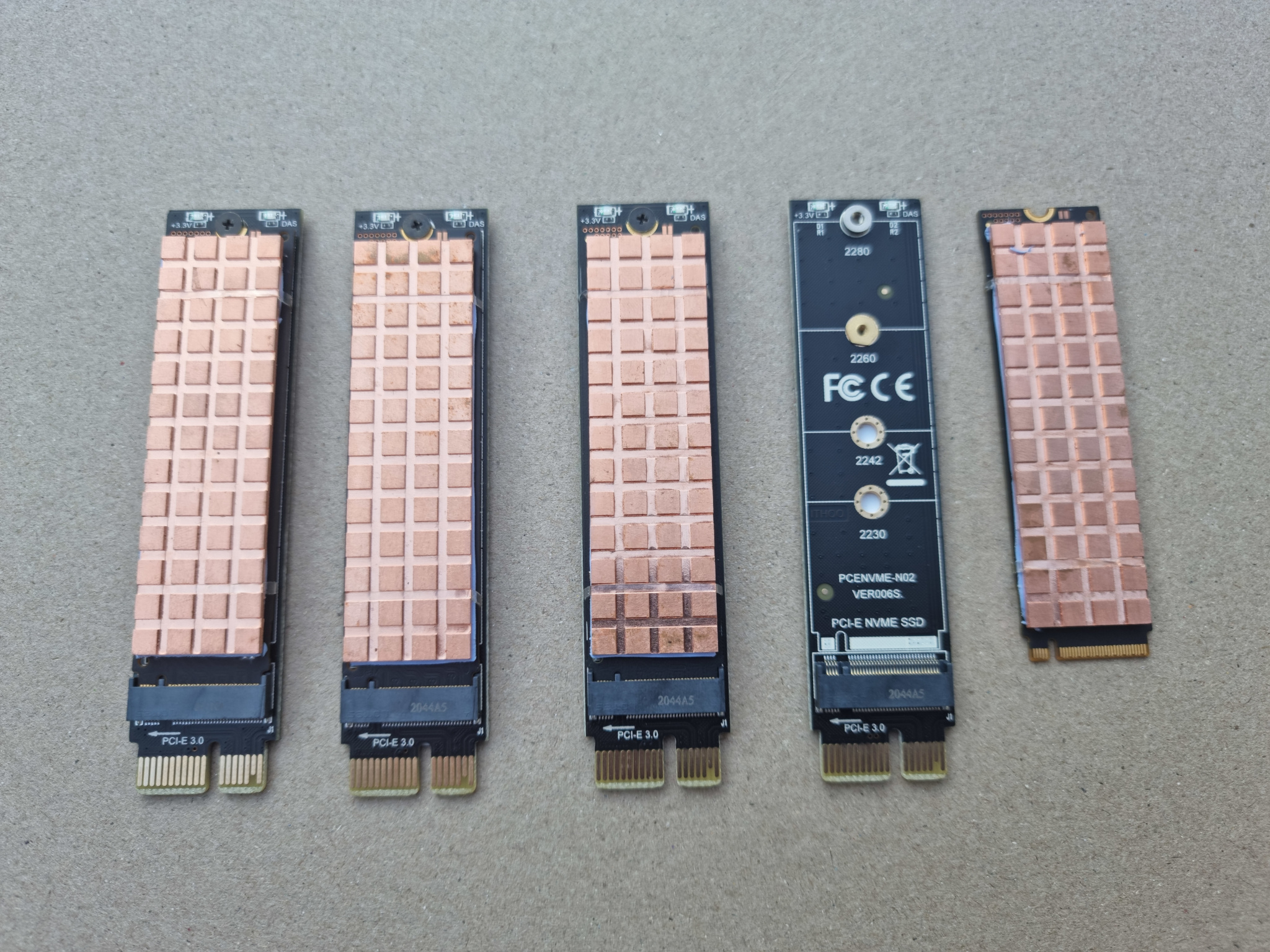
4 Disque nvme de 1To , avec Radiateur et Adaptateur nvme/PCI-e
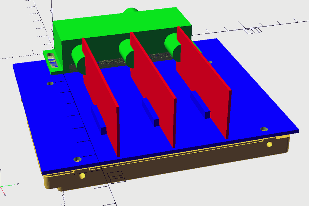
Impression 3D support pour les disques
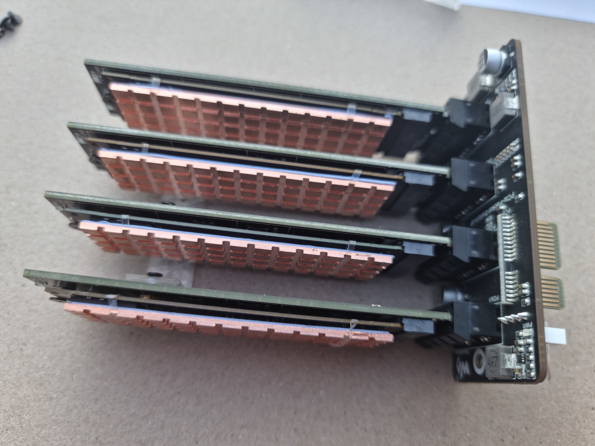
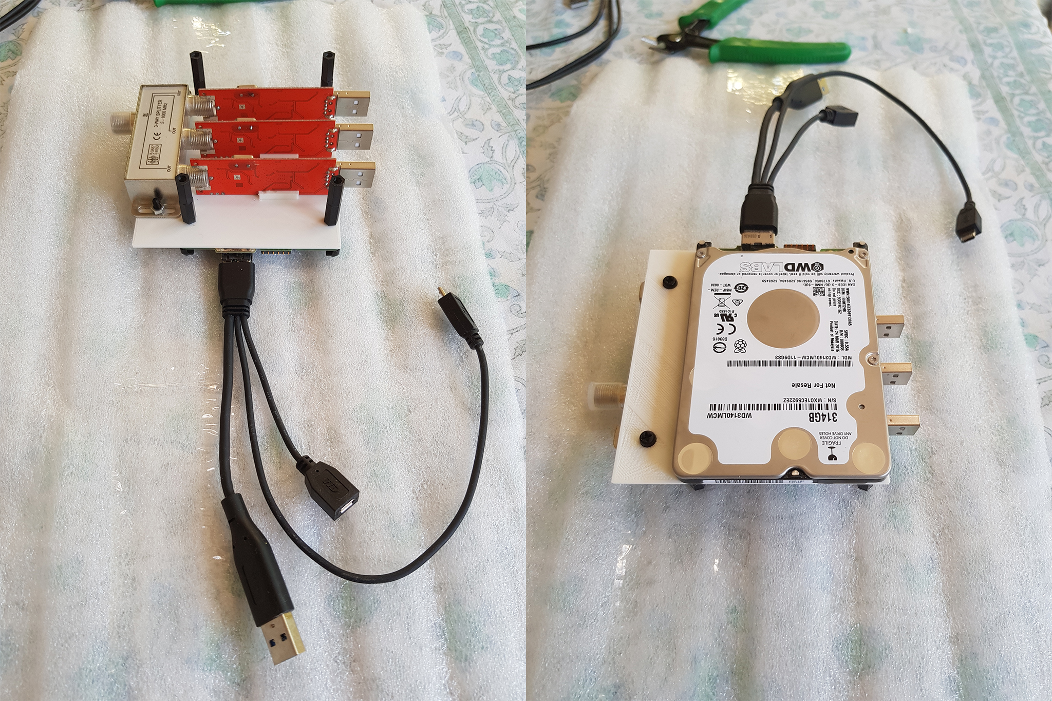
Montage des disques avec la carte extension PCI-e
pour le test ( et si j’intègre l’alimentation dans le boitier )
Dans la version finale les disque seront en position Horizontale , et le bloc d’aliemtation sera un bloc externe de 12v.
Catégorie : Non classé |
Commentaires fermés sur CM4 PI NAS nvme
Faire une plateforme de dev ( Electronique , arduino , esp8266 ) a partir d’un raspberry pi 4 , disque SSD et double écran .plutôt que dédier un PC portable
le boitier du 1er écran contiendras :
– un raspberry PI 4 8Go
– un SSD de 500 Go
– un module Buck down permettant de générer le 5V pour le Pi , Le SSD , les Hub USB
– un module buck down permettant de générer le 12V pour les 2 cartes controleur HDMI
– 2 cartes contrôleur HDMI / lvds pour gérer les 2 écrans
– 2 Hub USB 4 ports , un USB3.0 et un USB 2.0
– les 2 écrans ( qui sont des dalles de récuperation sur des pc portables HS ) seront relies ensemble avec une charnière qui permettra au 2eme écran de se se replier sur le 1er écran.
– le bloc d’alimentation sera externe ( pareil bloc de récupération d’un portable HS 19v 5A
création de l‘image Debian 64 bits depuis un poste linux (*****)
scripts a modifier pour les dernières versions du bootloader ( raspberrypi-bootloader_1.20200723-1_arm64.deb au 2020/08/04 ) et du kernel ( bcm2711-kernel-5.4.51.20200728.tar.xz au 2020/08/04 ) ,
dans stage2.sh modifier l’utilisateur debian par votre nom d’utilisateur dans mon cas : thierryadduser thierry
usermod -aG sudo,video,audio,cdrom thierry
pour l’instant ne pas activer l’option deskop (dans stage2.sh)
avant de démonter l’image fichiers a modifier :
fichier /boot/config.txt:
enable_uart=1
dtparam=audio=on
start_x=1
gpu_mem=128
[pi4]
dtoverlay=vc4-fkms-v3d
max_framebuffers=2
arm_64bit=1
# differentiate from Pi3 64-bit kernels
kernel=kernel8-p4.imgfichier /boot/cmdline.txt :
dwc_otg.lpm_enable=0 console=serial0,115200 console=tty1 root=/dev/sda2 rootfstype=ext4 elevator=deadline rootwait usb-storage.quirks=13fdc:3960:u ipv6.disable=1
j’avais des pb avec l’adaptateur USB3/SATA , j’ai du rajouter usb-storage.quirks=13fdc:3960:u dans le cmdline.txtfichier /etc/fstab :
proc /proc proc defaults 0 0
/dev/sda1 /boot vfat defaults 0 2
/dev/sda2 / ext4 defaults,noatime 0 1
transfert de l’image sur le SDD ( ici mon sdd est /dev/sdg a adapter selon votre config) :
sudo dd if=debian-rpi64.img of=/dev/sdg bs=1024k status=progress
brancher le SSD sur le Pi4 avec pour l’instant un moniteur hdmi / clavier / souris
si le Boot fonctionne on peux continuer sinon on recommence depuis le début .
on vas maintenant installer l’interface graphique ( une seule ):
apt install task-xfce-desktop -y # For XFCE
apt install task-gnome-desktop -y # For GNOME
apt install task-kde-desktop-y # For KDE Plasma
apt install task-mate-desktop -y # For MATE <== celle que j’ai choisi
apt install task-lxde-desktop -y # For LXDE
apt install task-lxqt-desktop -y # For LXQT
et on reboote le système , normalement l’interface graphique se lance .
encore quelques petites configurations ajout de logiciels
on lance un terminal :
sudo apt-get install devscripts build-essential lintian git
sudo mkdir /opt/Softs
sudo chown -R thierry: /opt/Softs
cd /opt/Softs
on vas récupérer sur https://github.com/RPi-Distro ce que l’on vas avoir besoin ; raspberrypi-sys-mods , raspi-config ,pi-bluetooth
git clone https://github.com/RPi-Distro/raspberrypi-sys-mods.git
git clone https://github.com/RPi-Distro/raspi-config.git
git clone https://github.com/RPi-Distro/pi-bluetooth.git
on compile :
cd pi-bluetooth
debuild -us -uc
cd ..
cd raspi-config
debuild -us -uc
cd ..
cd raspberrypi-sys-mods
debuild -us -uc
cd ..
on verifie que tout est compilé : ls -al *.deb
pi-bluetooth_0.1.13_all.deb raspberrypi-sys-mods_20200729_arm64.deb raspi-config_20200727_all.deb
on installe : sudo dpkg -i *.deb
si on as un message d’erreur de dépendance on lance sudo apt -f install , et tout devrais s’installer correctement
on installe la partie bluetooth :
sudo apt-get install bluetooth bluez blueman
La partie logicielle est pratiquement terminé , reste encore a installer kicad , arduino , codium et tous les gadgets nécessaire
Partie Matérielle
un clavier / Souris Officiel Raspberry Pi
Un raspberry Pi 4 8 Go
Un SSD 500Go + adaptateur USB/SATA
un hub USB 2.0 4 ports
un hub USB 3.0 4 ports
2 modules alim Buck down
2 dalles écrans 17″ de recupérations (modele LP173WD1 )
2 cartes contrôleurs HDMI
2 câbles HDMI / micro HDMI
***** => il existe maintenant une image 64bit de raspberry pi OS , https://downloads.raspberrypi.org/ raspios_arm64 ( version complète avec bureau ) et raspios_lite_arm64
Catégorie : Uncategorized |
Commentaires fermés sur Plateforme Dev avec Pi4 8Go – SSD 500 Go dual screen ( 15.6″ ou 17.3″ )
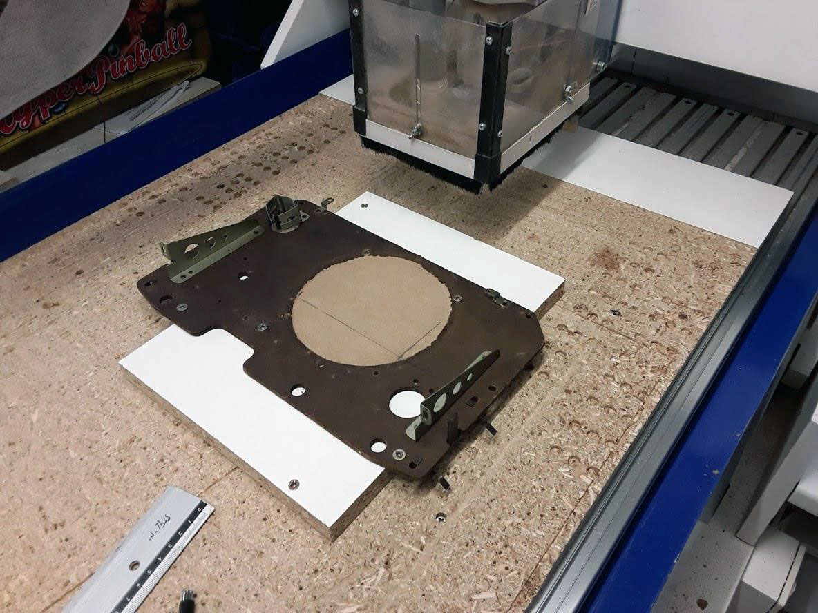
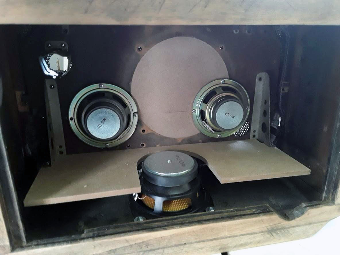
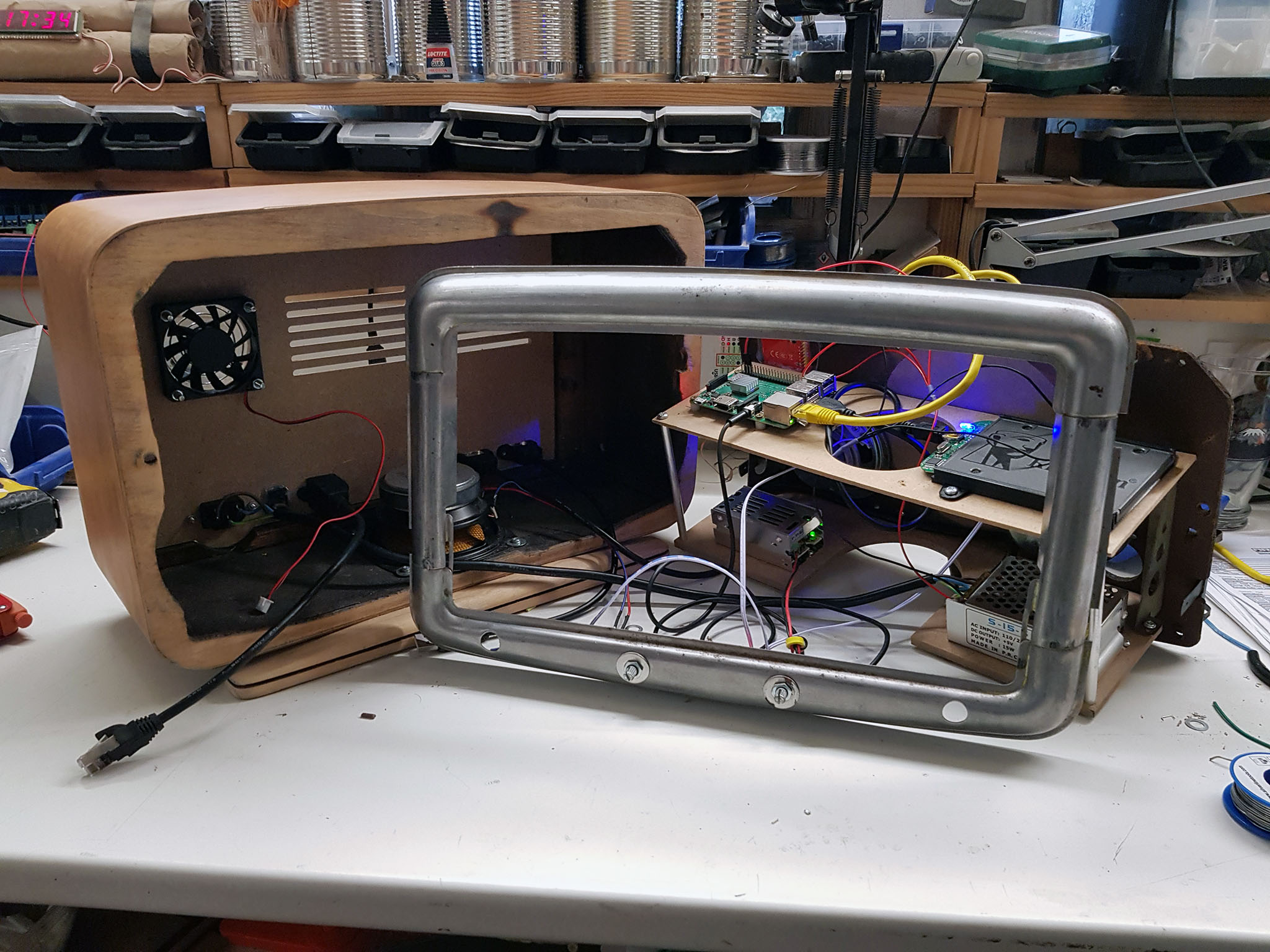
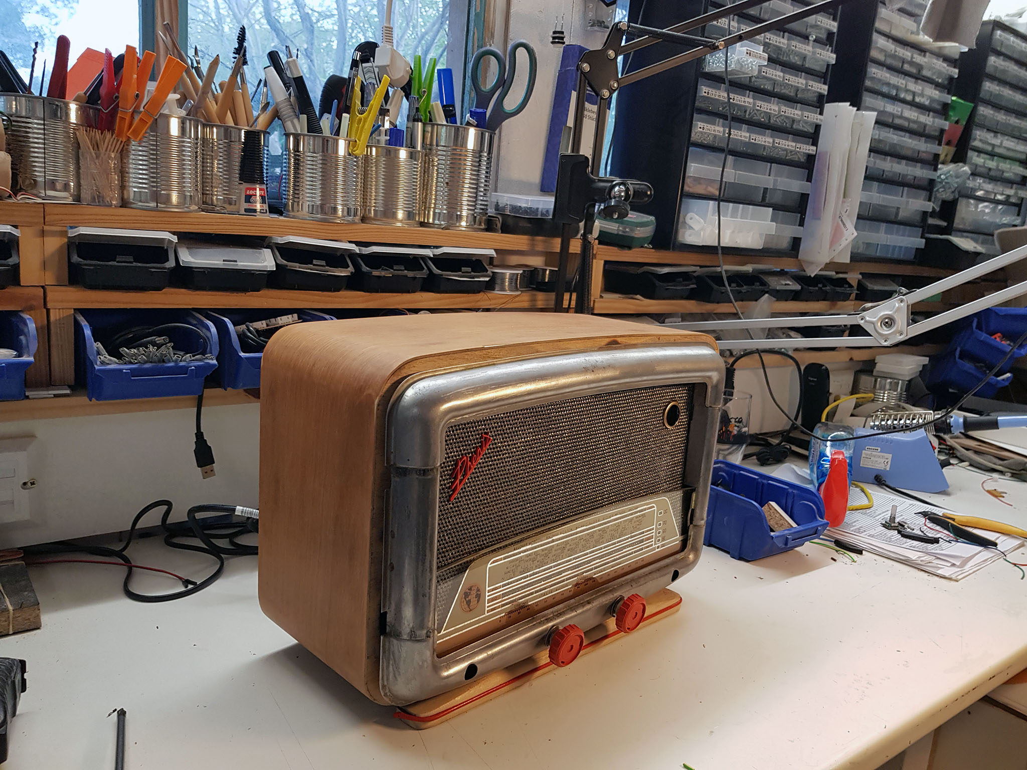
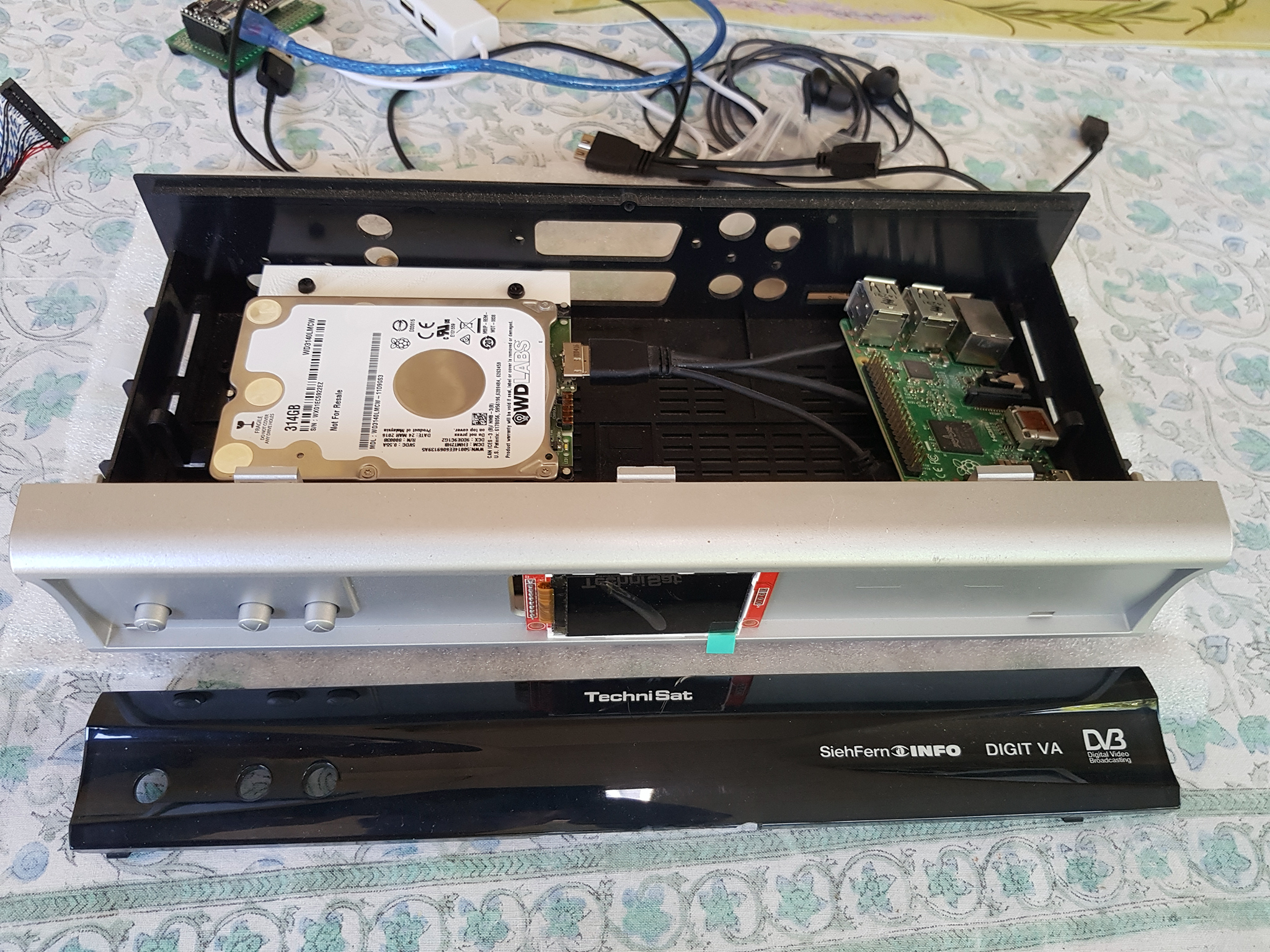
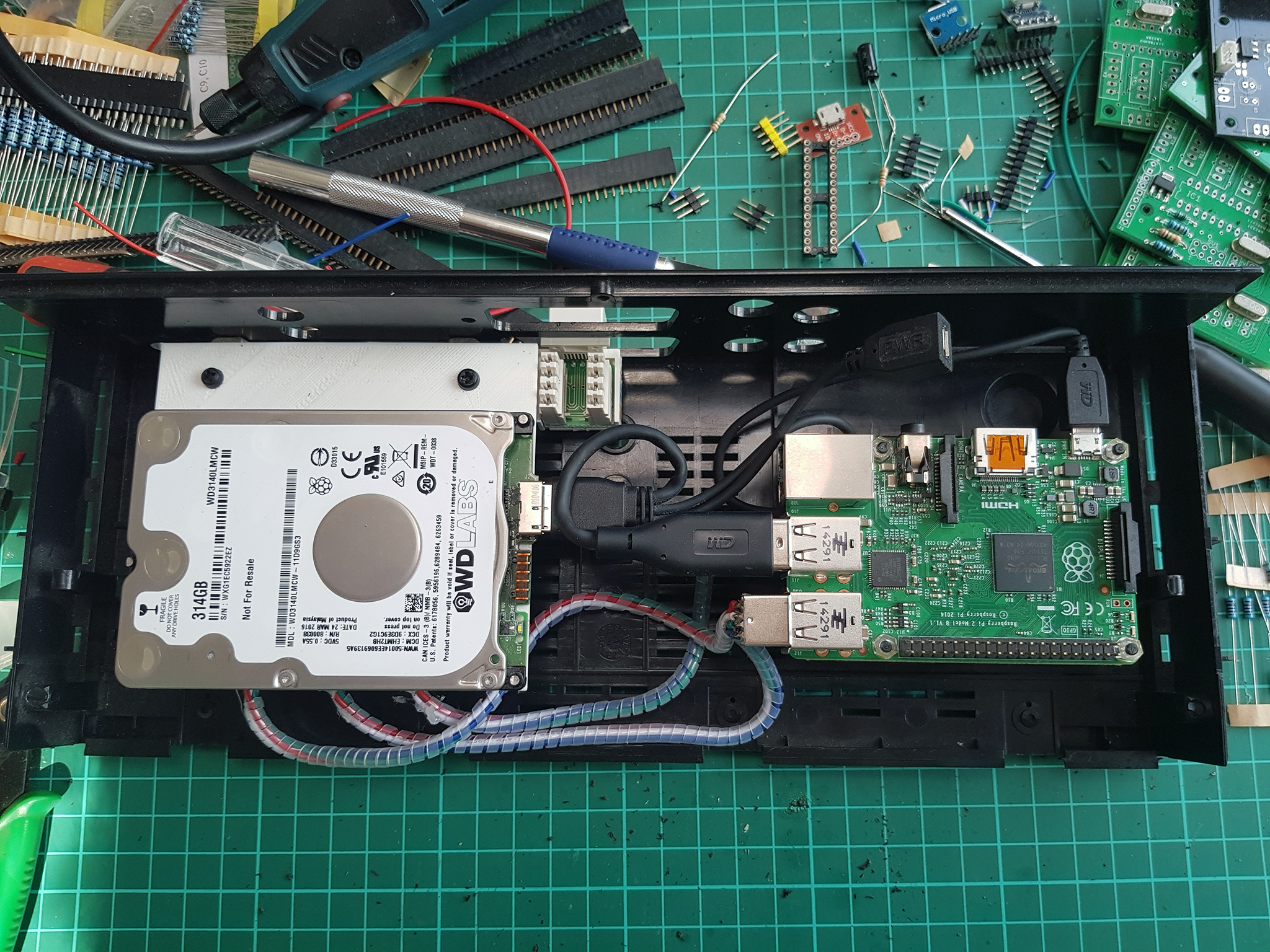
But: transformer un vieux poste radio a lampes HS des années 60/70 récupéré en vide grenier en poste mp3 avec un raspberry Pi.
Au niveau Matériel :
– un vieux poste radio a lampes HS des années 60/70
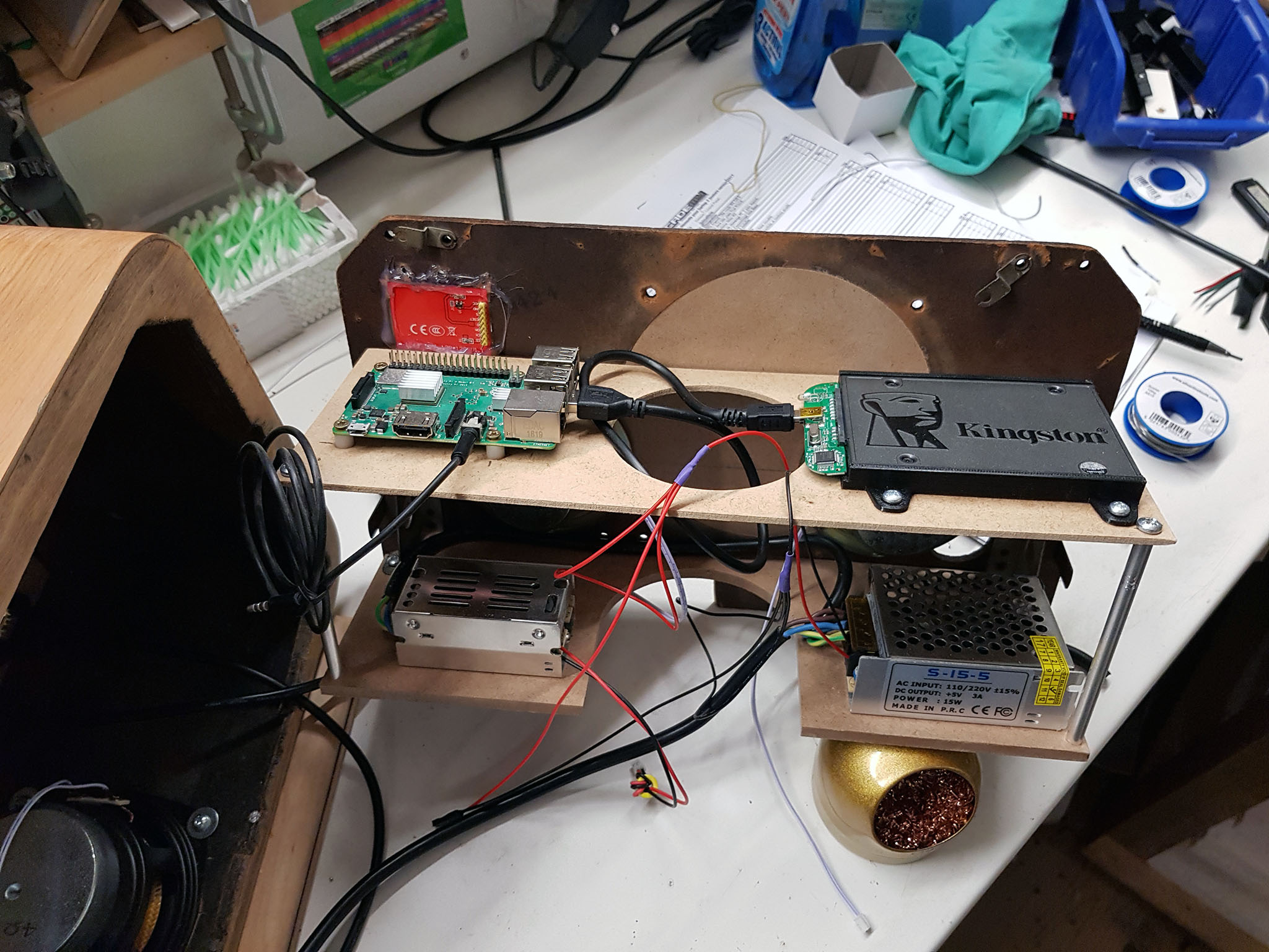
– un Raspberry Pi
– un ampli 2.1 20W
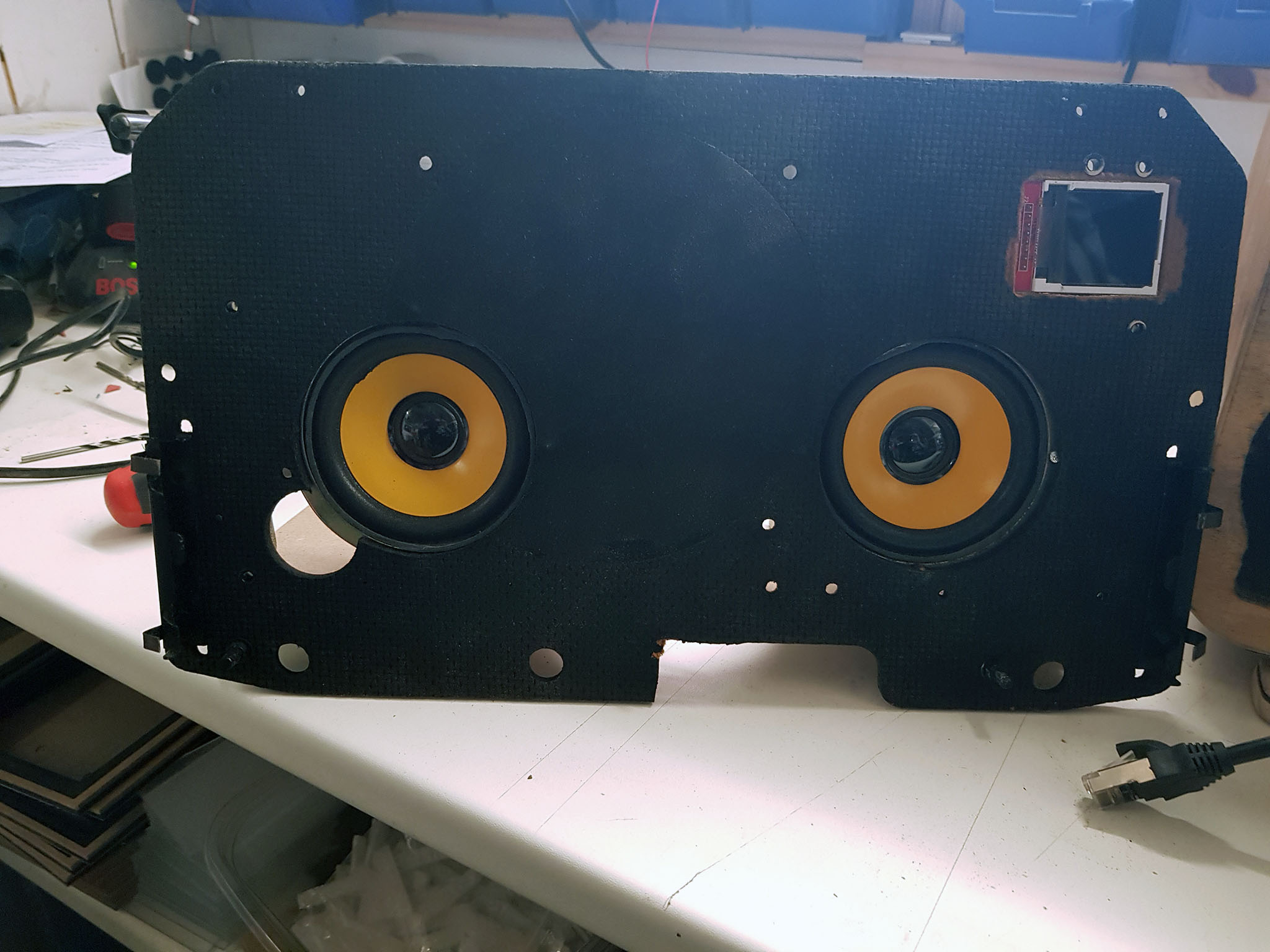
– 3 HP 5W
– un Afficheur 128×128 pixels
– deux encodeurs rotatifs
– un disque dur SSD avec adaptateur USB
– horloge RTC en I2C
– bande de led RGB
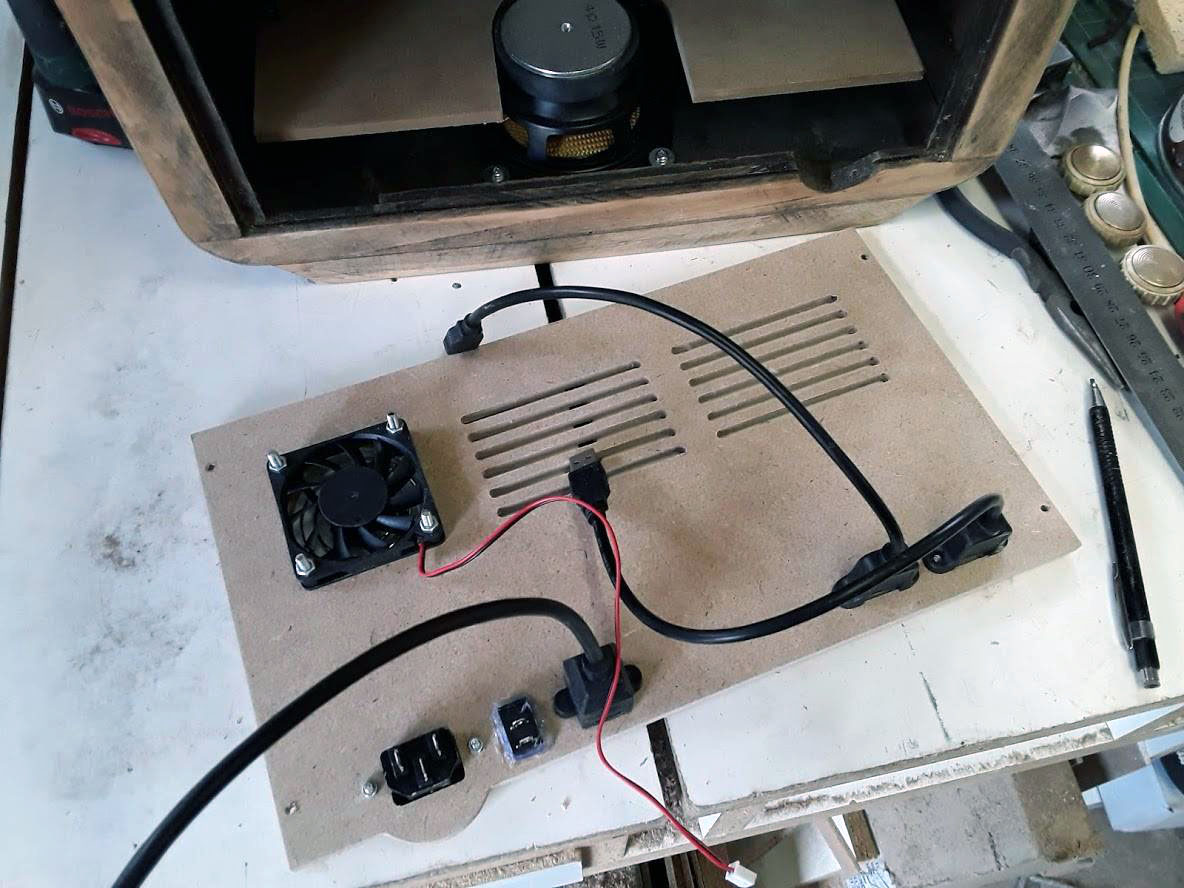
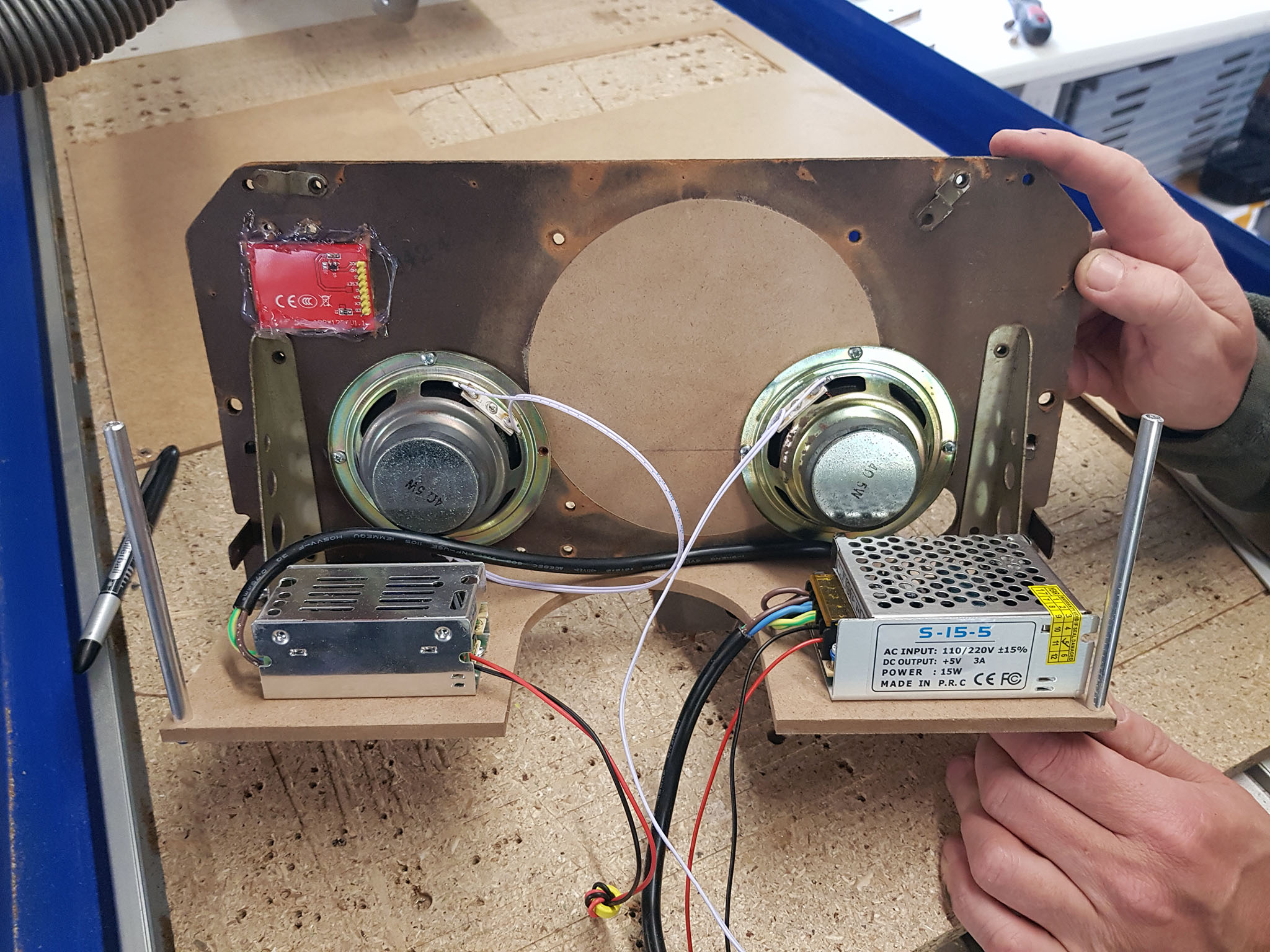
– deux alimentations 220v/5V ( une pour la partie Audio , l’autre pour la partie « numérique » 5A) et conneteur alimentation et interrupteur M/A
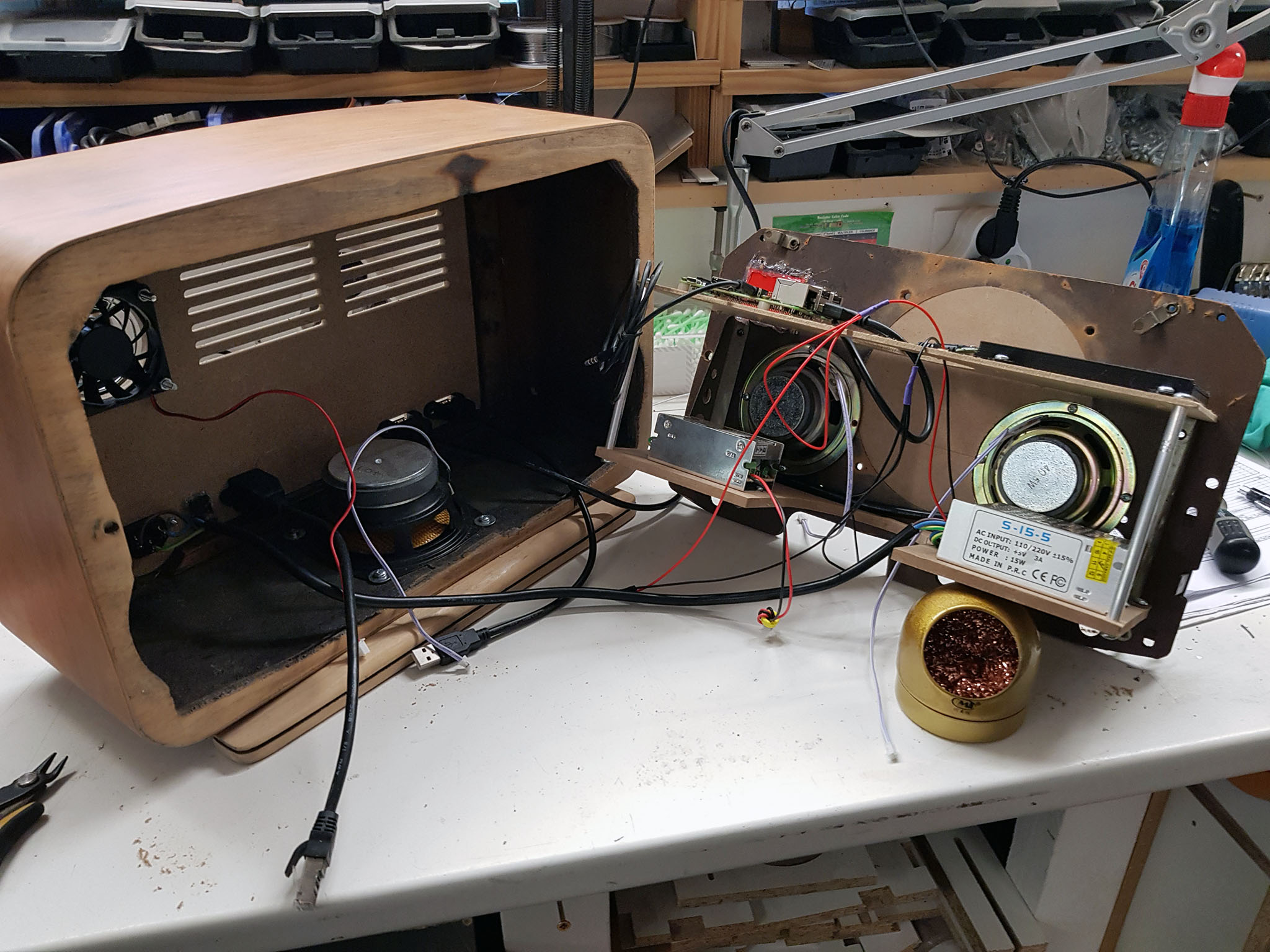
– un ventilateur 5V avec grille
– un disque dur SSD ( dans mon cas un 120Go)
Au niveau logiciel :
– Raspbian lite dernière version
– daemon mpd
– python3
– scripts divers ( gestion des encodeurs rotatif en émulation clavier UP,DOWN,LEFT,RIGHT,ENTER,PLAUY/PAUSE).
Photos de la transformation :
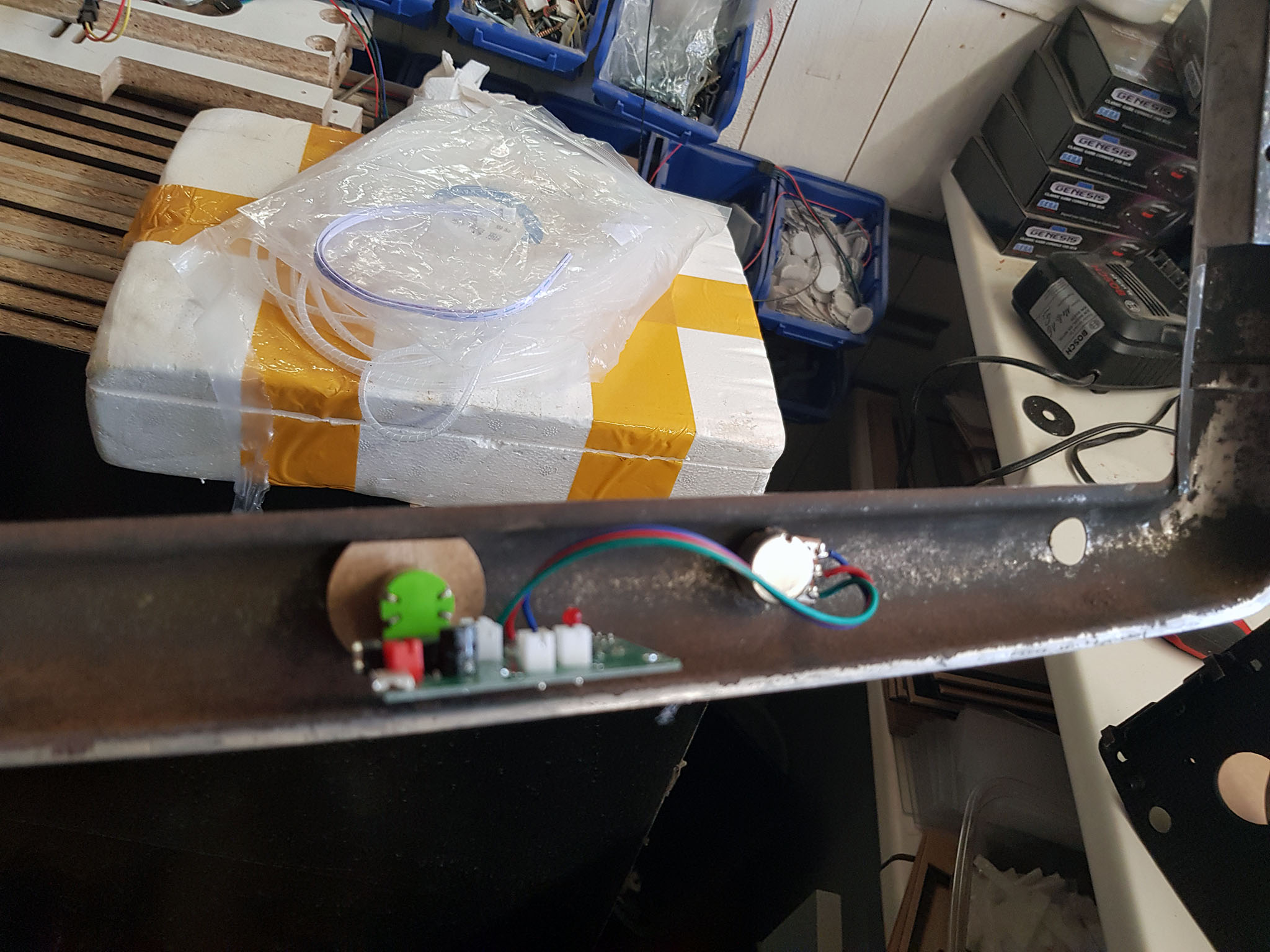
bon j’avoue en étant électronicien / informaticien , je déteste la partie « mécanique » ( boitier et autre ) , c’est donc mon beau-frère qui s’occupe de cette partie en plus ayant son Fablab perso il a tous les outils nécessaire
pour remplacer la lampe de « l’Œil magique » un afficheur 1.44” SPI de 128×128 pixels qui permettra d’afficher divers menu et aussi la pochette de la piste en cours a base de st7735 / ili9163
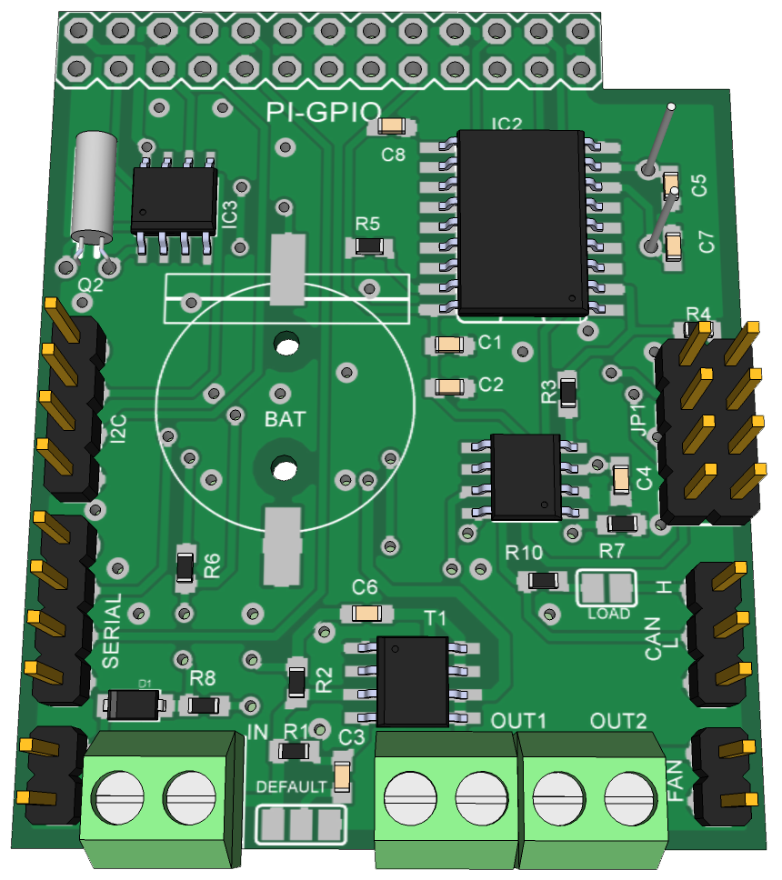
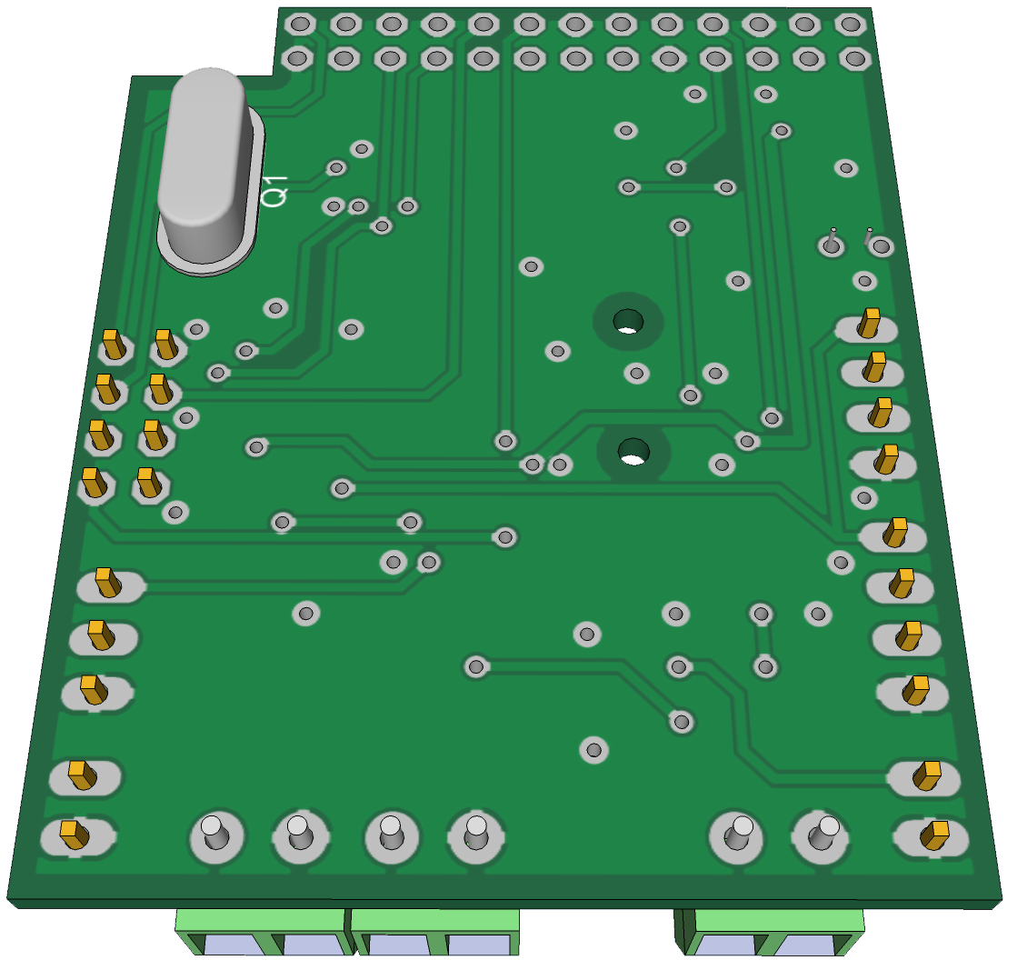
câblage des GPIO ( provisoire)
Name
Usage
Board
Usage
Name
3.3V
RTC.VCC
01 | | 02
LED.VCC
5V
GPIO02
RTC.SDA
03 | | 04
LCD.VCC
5V
GPIO03
RTC.SCL
05 | | 06
GND
GPIO04
07 | | 08
U_TXD
GPIO14
GND
RTC.GND
09 | | 10
U_RXD
GPIO15
GPIO17
ENC1.B
11 | | 12
SPI1_CE0
GPIO18
GPIO27
ENC1.A
13 | | 14
LCD.GND
GND
GPIO22
ENC1.SW
15 | | 16
LCD.LED
GPIO23
3.3V
17 | | 18
LCD.A0
GPIO24
GPIO10
LCD.SDA
19 | | 20
GND
GPIO09
21 | | 22
LCD.RST
GPIO25
GPIO11
LCD.SCK
23 | | 24
LCD.CS
GPIO08
GND
ENC1.GND
25 | | 26
GPIO07
ID_SD0
*
27 | | 28
*
ID_SC1
GPIO05
ENC2.A
29 | | 30
FAN.GND
GND
GPIO06
ENC2.B
31 | | 32
FAN.PWM
GPIO12
GPIO13
ENC2.SW
33 | | 34
LED.GND
GND
GPIO19
SPI1_MISO
35 | | 36
GPIO16
GPIO26
37 | | 38
LED.DI
GPIO20
GND
ENC2.GND
39 | | 40
SPI1_SCLK
GPIO21
installation logicielle , j’ai décidé de me passer de carte SD sur le Raspberry et booter directement sur le SSD ( voir article frambroise 314 )
j’ai fait 3 partions sur le hdd (/dev/sda1 vfat 100M , /dev/sda2 ext4 8Go , /dev/sda3 ext4 le reste du disque pour stockage des fichiers audios )
mon /etc/fstab
cd /opt/scripts
wget https://www.ympd.org/downloads/ympd-1.2.3-armhf.tar.bz2
tar -xvf ympd-1.2.3-armhf.tar.bz2
sudo ./ympd --webport 80
partage dossier réseau ( /etc/samba/smb.conf )
#======================= Global Settings =======================
[global]
   workgroup = WORKGROUP
   dns proxy = no
   log file = /var/log/samba/log.%m
   max log size = 1000
   syslog = 0
   panic action = /usr/share/samba/panic-action %d
   server role = standalone server
   passdb backend = tdbsam
   obey pam restrictions = yes
   unix password sync = yes
   passwd program = /usr/bin/passwd %u
   passwd chat = *Enter\snew\s*\spassword:* %n\n *Retype\snew\s*\spassword:* %n\n *password\supdated\ssuccessfully* .
   pam password change = yes
   map to guest = bad user
   usershare allow guests = yes

#======================= Share Definitions =======================
[home]
   browseable = yes
   create mask = 0700
   directory mask = 0700
   guest ok = yes
   path = /home/pi
   force user =  pi
   force group = pi
   read only = No

[scripts]
   browseable = yes
   create mask = 0700
   directory mask = 0700
   guest ok = yes
   path = /opt/scripts
   force user =  pi
   force group = pi
   read only = No

[Media]
   browseable = yes
   create mask = 0700
   directory mask = 0700
   guest ok = yes
   path = /var/lib/mpd/
   force user =  mpd
   force group = audio
   read only = No
gestion de led RGB ws2812 , pour cela on va activer le 2eme port SPI ( raspberry pi 3
dans /boot/config.txt ajouter/modifier
spidev.bufsiz=32768
dtoverlay=spi1-1cs
ensuite on vas ajouter py-spidev et ws2812-spi
sudo apt install python-spidev python3-spidev

cd /opt/scripts
git clone https://github.com/doceme/py-spidev.git
cd py-spidev
make
make install

cd /opt/scripts
git clone https://github.com/joosteto/ws2812-spi.git
cd ws2812-spi
en fonction du Pi utilisé il faut modifier le fichier ws2812.py , dans def write2812_numpy4(spi,data): commenter toutes les lignes spi.xfer et de-commenter celle ci : spi.xfer(tx.tolist(), int(4/.55e-6))
ensuite
sudo python setup.py install
on vas tester le bandeau :
cd /opt/scripts
nano loop.py
dans mon cas il y auras 20 led RGB ws2812 donc :
import spidev
import ws2812
import time
import getopt

def test_loop(spi, nLED=8, intensity=20):
    stepTime=0.1
    iStep=0
    while True:
        d=[[0,0,0]]*nLED
        d[iStep%nLED]=[intensity]*3
        ws2812.write2812(spi, d)
        iStep=(iStep+1)%nLED
        time.sleep(stepTime)

if __name__=="__main__":
    spi = spidev.SpiDev()
    spi.open(1,0)

    test_loop(spi, nLED=20)
cd /opt/scripts
git clone https://github.com/nvbn/soundlights.git
./autogen.sh
./configure
make
sudo make install
création du fichier de config : nano /opt/scripts/config.led :
But: monter un serveur Domoticz avec des modules sonoff a base de esp8266 pour faire des TD / TP en BTS SN ( ancien BTS Electronique ).
le Raspberry communique avec les modules sonoff avec un réseau wifi séparé du réseau local.
Matériel nécessaire :
– Un Raspberry PI 3 ( ou un autre avec dongle wifi ) avec carte SD de 8Go ( actuellement ~3.5Go utilisé )
– Un écran 7″ officiel tactile pour le Raspberry pi ( optionnel )
– plusieurs modules « SonOff » pour la partie purement Domotique ( attention présence de tension secteur 220v )
le tuto est découpée en plusieurs parties a suivre dans l’ordre
-Installation du Raspberry PI
-Début du paramétrage
-Installation de Node-Red
-Installation de Webmin
-Hotspot Wifi et DHCP
-Serveur Web nginx
-Installation phpmyadmin depuis les sources
-Configuration de Samba
-Installation de eZServerMonitor
-l’ecran 7″ tactile officiel du Rapsberry pi
-Test divers
-Mise à jour de domoticz par tache cron ( Optionel )
-Sauvegarde des bases de données SQL
Partie 1 ) Installation du Raspberry PI
On récupère l’image « raspbian lite » sur https://www.raspberrypi.org/downloads/raspbian/
Une fois l’image récupérée on va la copier sur la carte SD , avec Win32diskimage ou autre logiciel
On accède a la partition FAT32 de la carte SD et on crée un fichier texte que l’on appelle ssh , cela activera le serveur ssh du Pi au démarrage
On met la carte SD dans le Raspberry et on démarre le système , si l’écran est branché on peux suivre le processus , sinon attendre environ 5mn
On Scanne son réseau avec un utilitaire ( dans mon cas Angry Ip Scanner => http://angryip.org/ ) pour trouver l’adresse du PI
on se connecte en SSH ( utilisateur: pi , mot de passe: raspberry )
Dans le reste du Tuto lorsqu’il y a des lignes de commandes, celles commençant par $ sont lancées avec l’utilisateur pi et celles commençant par # par l’utilisateur root ( ne pas taper $ ou # lors des commandes ). et lorsque dans les lignes de commandes si en fin de ligne il y a \ cela veux dire que la commande continue sur la ligne suivante il faut tous taper sur une seule ligne et de pas mettre le \ .
quand je dis on edite le fichier x , cela veux dire : sudo nano x
on vas changer locale , timezone , key, wifi
$sudo raspi-config
on vas changer le mot de passe du compte root => « Domotic »
$sudo passwd root
Mise a jour kernel & firmware
$sudo rpi-update
Une fois a jour on reboot et on enlève l’ancien firmware (4.14.34 dans mon cas ) , faire ls -al /lib/modules pour voir les versions installées . on peux meme enlever celui qui ne se termine pas pas v7+
un petit reboot et on vas commencer le paramétrage
Partie 2 ) Début du paramétrage
on vas autoriser tous les utilisateur a lancer le serveur graphique
$sudo dpkg-reconfigure xserver-xorg-legacy
on vas sécuriser les bases SQL ( Domotic en mdp , supprimer les bases test , autoriser le remote …)
Remove anonymous users? => Y
Disallow root login remotely? => N
Remove test database and access to it? => Y
$sudo mysql_secure_installation
$echo "update mysql.user set plugin = 'mysql_native_password' where user='root';" | sudo mysql -u root -p
maintenant on vas installer Domoticz. Plus besoin d’installer les sources et de compiler
$sudo curl -L install.domoticz.com | bash
en réseau local pas besoin de IPV6 , on vas le desactiver , editer /etc/sysctl.conf et ajouter a la fin :
# désactivation de ipv6 pour toutes les interfaces
net.ipv6.conf.all.disable_ipv6 = 1
# désactivation de l’auto configuration pour toutes les interfaces
net.ipv6.conf.all.autoconf = 0
# désactivation de ipv6 pour les nouvelles interfaces (ex:si ajout de carte réseau)
net.ipv6.conf.default.disable_ipv6 = 1
# désactivation de l’auto configuration pour les nouvelles interfaces
net.ipv6.conf.default.autoconf = 0
on editer /etc/webmin/miniserv.conf , et changer ssl=1 en ssl=0
$sudo service webmin restart
se connecter sur la page de webmin http://ip_du_pi:1000 ( user: root , mdp : Domotic)
passer webmin en Francais : menu webmin , Configuration de Webmin , langue
télécharger le module de gestion de nginx sur https://www.justindhoffman.com/sites/justindhoffman.com/files/nginx-0.10.wbm_.gz
ajouter le module dans webmin : menu webmin , Configuration de Webmin , modules webmin ,
Partie 5 ) Hotspot Wifi et DHCP
$sudo nano /etc/dhcpcd.conf
ajouter a la fin: le PI chercheras un dhcp sur son interface filaire , mais pour la partie wifi c’est lui qui serat serveur DHCP
denyinterfaces wlan0
on attaque la partie hotspot en éditant /etc/hostapd/hostapd.conf
si vous voulez changer le code wifi ou le ssid c’est le moment
config serveur dhcp sur wlan0 bloc adr de 192.168.254.10 -> 192.168.254.200 . On vas forcer l’ip de wlan0 , on édite /etc/network/interfaces
et ajouter :
auto lo
iface lo inet loopback

allow-hotplug eth0
iface eth0 inet dhcp

allow-hotplug wlan0
iface wlan0 inet static
    address 192.168.254.1
    netmask 255.255.255.0
    network 192.168.254.0
    broadcast 192.168.254.255
interface=wlan0      # Use interface wlan0
#no-resolv
no-poll

listen-address=192.168.254.1 # Explicitly specify the address to listen on
bind-interfaces      # Bind to the interface to make sure we aren't sending things elsewhere
server=8.8.8.8       # Forward DNS requests to Google DNS
server=192.168.254.1 #
domain-needed        # Don't forward short names
bogus-priv           # Never forward addresses in the non-routed address spaces.
addn-hosts=/etc/dnsmasq_static_hosts.conf

# Assign IP addresses between 192.168.254.10 and 192.168.254.200 with a 12 hour lease time
dhcp-range=192.168.254.10,192.168.254.200,12h

# force appariel adr mac b4:7c:9c:fe:11:50 => IP 192.168.254.201
dhcp-host=b4:7c:9c:fe:11:50,192.168.254.201
Editez /etc/default/hostapd , ajouter :
DAEMON_CONF="/etc/hostapd/hostapd.conf"
dans /etc/sysctl.conf ajouter
net.ipv4.ip_forward=1
le Pi vas servir de serveur ntp (time) pour les modules domotiques sonoff , on édite /etc/ntp.conf et on ajoute
$sudo service hostapd start
$sudo service dnsmasq start
Partie 6 ) Serveur Web nginx
Au lieu d’utiliser Apache en serveur Web on vas utiliser nginx ( moins gourmand en mémoire) , ne gérant pas l’activation / désactivation des sites virtuels comme apache on vas creer un fichier nginx_modsite et le rendre executable
#!/bin/bash

##
#  File:
#    nginx_modsite
#  Description:
#    Provides a basic script to automate enabling and disabling websites found
#    in the default configuration directories:
#      /etc/nginx/sites-available and /etc/nginx/sites-enabled
#    For easy access to this script, copy it into the directory:
#      /usr/local/sbin
#    Run this script without any arguments or with -h or --help to see a basic
#    help dialog displaying all options.
##

# Copyright (C) 2010 Michael Lustfield <mtecknology@ubuntu.com>

# Redistribution and use in source and binary forms, with or without
# modification, are permitted provided that the following conditions
# are met:
# 1. Redistributions of source code must retain the above copyright
#    notice, this list of conditions and the following disclaimer.
# 2. Redistributions in binary form must reproduce the above copyright
#    notice, this list of conditions and the following disclaimer in the
#    documentation and/or other materials provided with the distribution.
#
# THIS SOFTWARE IS PROVIDED BY AUTHOR AND CONTRIBUTORS ``AS IS'' AND
# ANY EXPRESS OR IMPLIED WARRANTIES, INCLUDING, BUT NOT LIMITED TO, THE
# IMPLIED WARRANTIES OF MERCHANTABILITY AND FITNESS FOR A PARTICULAR PURPOSE
# ARE DISCLAIMED.  IN NO EVENT SHALL AUTHOR OR CONTRIBUTORS BE LIABLE
# FOR ANY DIRECT, INDIRECT, INCIDENTAL, SPECIAL, EXEMPLARY, OR CONSEQUENTIAL
# DAMAGES (INCLUDING, BUT NOT LIMITED TO, PROCUREMENT OF SUBSTITUTE GOODS
# OR SERVICES; LOSS OF USE, DATA, OR PROFITS; OR BUSINESS INTERRUPTION)
# HOWEVER CAUSED AND ON ANY THEORY OF LIABILITY, WHETHER IN CONTRACT, STRICT
# LIABILITY, OR TORT (INCLUDING NEGLIGENCE OR OTHERWISE) ARISING IN ANY WAY
# OUT OF THE USE OF THIS SOFTWARE, EVEN IF ADVISED OF THE POSSIBILITY OF
# SUCH DAMAGE.

##
# Default Settings
##

NGINX_CONF_FILE="$(awk -F= -v RS=' ' '/conf-path/ {print $2}' <<< $(nginx -V 2>&1))"
NGINX_CONF_DIR="${NGINX_CONF_FILE%/*}"
NGINX_SITES_AVAILABLE="$NGINX_CONF_DIR/sites-available"
NGINX_SITES_ENABLED="$NGINX_CONF_DIR/sites-enabled"
SELECTED_SITE="$2"

##
# Script Functions
##

ngx_enable_site() {
    [[ ! "$SELECTED_SITE" ]] &&
        ngx_select_site "not_enabled"

    [[ ! -e "$NGINX_SITES_AVAILABLE/$SELECTED_SITE" ]] &&
        ngx_error "Site does not appear to exist."
    [[ -e "$NGINX_SITES_ENABLED/$SELECTED_SITE" ]] &&
        ngx_error "Site appears to already be enabled"

    ln -sf "$NGINX_SITES_AVAILABLE/$SELECTED_SITE" -T "$NGINX_SITES_ENABLED/$SELECTED_SITE"
    ngx_reload
}

ngx_disable_site() {
    [[ ! "$SELECTED_SITE" ]] &&
        ngx_select_site "is_enabled"

    [[ ! -e "$NGINX_SITES_AVAILABLE/$SELECTED_SITE" ]] &&
        ngx_error "Site does not appear to be \'available\'. - Not Removing"
    [[ ! -e "$NGINX_SITES_ENABLED/$SELECTED_SITE" ]] &&
        ngx_error "Site does not appear to be enabled."

    rm -f "$NGINX_SITES_ENABLED/$SELECTED_SITE"
    ngx_reload
}

ngx_list_site() {
    echo "Available sites:"
    ngx_sites "available"
    echo "Enabled Sites"
    ngx_sites "enabled"
}

##
# Helper Functions
##

ngx_select_site() {
    sites_avail=($NGINX_SITES_AVAILABLE/*)
    sa="${sites_avail[@]##*/}"
    sites_en=($NGINX_SITES_ENABLED/*)
    se="${sites_en[@]##*/}"

    case "$1" in
        not_enabled) sites=$(comm -13 <(printf "%s\n" $se) <(printf "%s\n" $sa));;
        is_enabled) sites=$(comm -12 <(printf "%s\n" $se) <(printf "%s\n" $sa));;
    esac

    ngx_prompt "$sites"
}

ngx_prompt() {
    sites=($1)
    i=0

    echo "SELECT A WEBSITE:"
    for site in ${sites[@]}; do
        echo -e "$i:\t${sites[$i]}"
        ((i++))
    done

    read -p "Enter number for website: " i
    SELECTED_SITE="${sites[$i]}"
}

ngx_sites() {
    case "$1" in
        available) dir="$NGINX_SITES_AVAILABLE";;
        enabled) dir="$NGINX_SITES_ENABLED";;
    esac

    for file in $dir/*; do
        echo -e "\t${file#*$dir/}"
    done
}

ngx_reload() {
    read -p "Would you like to reload the Nginx configuration now? (Y/n) " reload
    [[ "$reload" != "n" && "$reload" != "N" ]] && invoke-rc.d nginx reload
}

ngx_error() {
    echo -e "${0##*/}: ERROR: $1"
    [[ "$2" ]] && ngx_help
    exit 1
}

ngx_help() {
    echo "Usage: ${0##*/} [options]"
    echo "Options:"
    echo -e "\t<-e|--enable> \tEnable site"
    echo -e "\t<-d|--disable> \tDisable site"
    echo -e "\t<-l|--list>\t\tList sites"
    echo -e "\t<-h|--help>\t\tDisplay help"
    echo -e "\n\tIf  is left out a selection of options will be presented."
    echo -e "\tIt is assumed you are using the default sites-enabled and"
    echo -e "\tsites-disabled located at $NGINX_CONF_DIR."
}

##
# Core Piece
##

case "$1" in
    -e|--enable)    ngx_enable_site;;
    -d|--disable)   ngx_disable_site;;
    -l|--list)  ngx_list_site;;
    -h|--help)  ngx_help;;
    *)      ngx_error "No Options Selected" 1; ngx_help;;
esac
on vas supprimer les config par defaut de nginx
$sudo rm /etc/nginx/sites-available/default et /etc/nginx/sites-enabled/default
On edite /var/www/eZServerMonitor-2.5/conf/esm.config.json , enlever la section ping dans services enlever email server , ftp et ajouter apres la section Web Server :
relancer le PI , maintenant le PI lance firefox au démarrage avec la page www.domo.home
Partie 11 ) Test divers
se connecter sur le wifi du PI depuis une tablette ou un smartphone et tester les sites suivants :
domo.home,www.domo.home, => Serveur Web Domoticz
sql.domo.home,www.sql.domo.home, => Admnistration des bases SQL
webmin.domo.home,www.webmin.domo.home, => Webmin pour configuration serveur
nofuss.domo.home,www.nofuss.domo.home, ** => Pour maj des firmware des modules SonOff en cours de Dev
node.domo.home,www.node.domo.home, => pour faire des Scripts en NodeRed
status.domo.loca,www.status.domo.home, => affichage status du PI , cpu , memoire , espace disque
system.domo.home,www.system.domo.home** => interface générale pour lancer les sites
** devrait sortir un message d’erreur pas pas encore de fichiers/dossiers crées
sur un PC windows en connexion filaire éditer le fichier C:\Windows\System32\drivers\etc et ajouter , en remplaçant 192.168.xxx.xxx par l’IP ‘filaire’ du PI
pour eviter le message « — Warning: Skipping the data of table mysql.event. Specify the –events option explicitly. »
$sudo nano /etc/mysql/conf.d/automysqlbackup.cnf
ensuite insérer le code suivant :
[mysqldump]
events
ignore-table = mysql.events
Partie 14 ) xxxxx
En cours d’éciture
Partie 15 ) xxxxx
En cours d’éciture
Conclusion ( provisoire ) Reste a faire les dossier /var/www/nofuss.domo.home et /var/www/system et pour ceux qui sont perdu , un fichier .gz avec tous les fichiers conf modifiés pour injection directe dans le PI ( il faudras faire juste les parties 1,2,3 et 4 ) sera disponible très bientôt
( rotate=90 a adapter selon position afficheur ) .On edite aussi cmdline.txt
$sudo nano /boot/cmdline.txt
et on ajoute en fin de ligne :
fbcon=map:10
on reboote et normalement l’afficheur fonctionne , si ne marche pas bien vérifier le câblage et que c’est bien un ili9341
Pour tester le rétro-éclairage (1:OFF , 0:ON) : ( pour plus d’info voir : https://github.com/notro/fbtft/wiki/Backlight )
$echo 1 | sudo tee /sys/class/backlight/*/bl_power
$echo 0 | sudo tee /sys/class/backlight/*/bl_power
Installation de samba et HDD USB ( en cours ………)
………….
…………………
Catégorie : Hardware, Software |
Commentaires fermés sur Serveur Tvheadend avec stockage ( Partie 1 – installation tvheadend et epg )
Encore un petit manque dans le monde du raspberry pi , un bouton arrêt ( propre , pas en coupant a la sauvage l’alimentation du PI ).
besoin d’avoir python et rpi.gpio installé , un boutton poussoir (dans cet exemple cablé entre le GPIO17 et gnd )
script pour attendre appuie sur le bouton et lancer shutdown lorsque l’on appuie sur le bouton : pishutdown.py =>
#!/usr/bin/python
# Import the modules to send commands to the system and access GPIO pins
import RPi.GPIO as gpio
import os
#set up GPIO using BCM numbering
gpio.setmode(gpio.BCM)
#Set up pin 7 as an input
gpio.setup(17, gpio.IN, pull_up_down = gpio.PUD_UP)
# Set up an interrupt to look for pressed button
gpio.wait_for_edge(17, gpio.FALLING)
# Shutdown
os.system('shutdown now -h')
script qui va se lancer au demérrage du PI : pishutdown.sh =>
#!/bin/sh
cd /
cd home/tools
python pishutdown.py
cd /
puis chmod +x pishutdown.sh
on édite le fichier /etc/rc.local
/home/tools/pishutdown.sh &
a rajouter avant la ligne exit 0 , a adapter selon l’endroit ou vous copiez les 2 fichiers ( pishutdown.py , pishutdown.sh) et du gpio utilisé .
Catégorie : Hardware, Software |
Commentaires fermés sur Shutdown Raspberry PI par gpio