RadioPi
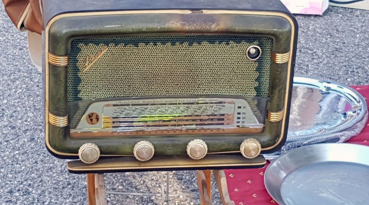
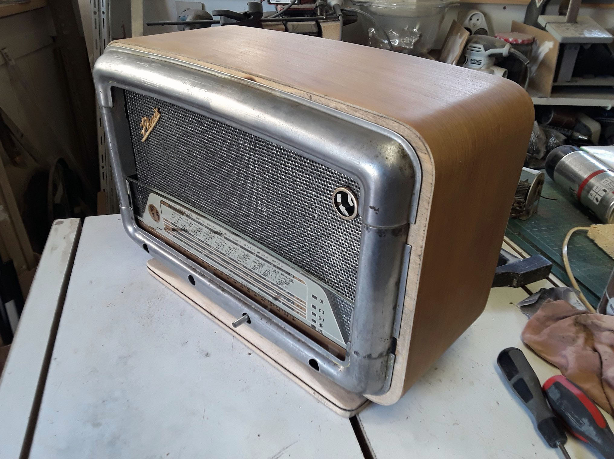
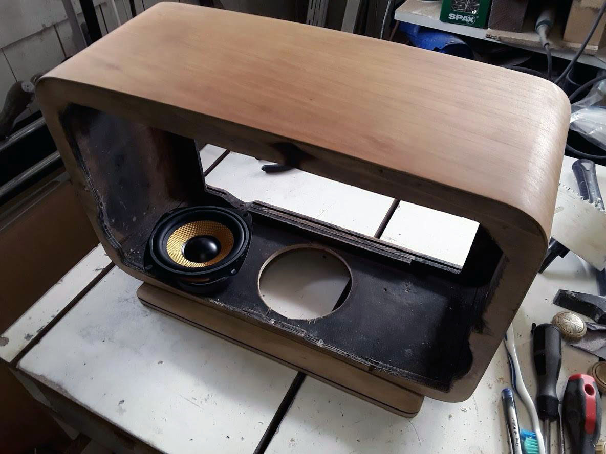
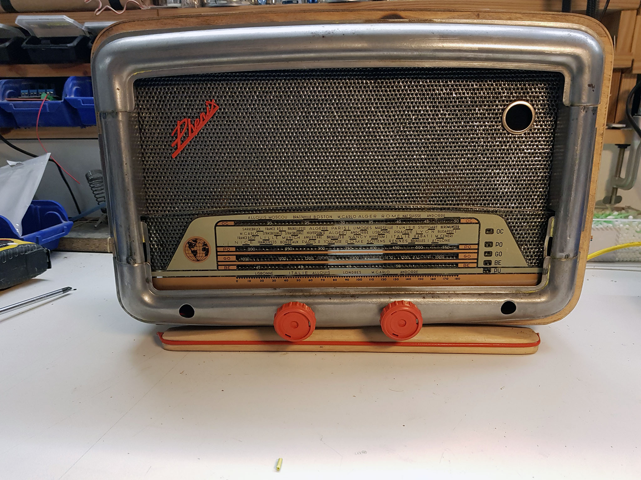
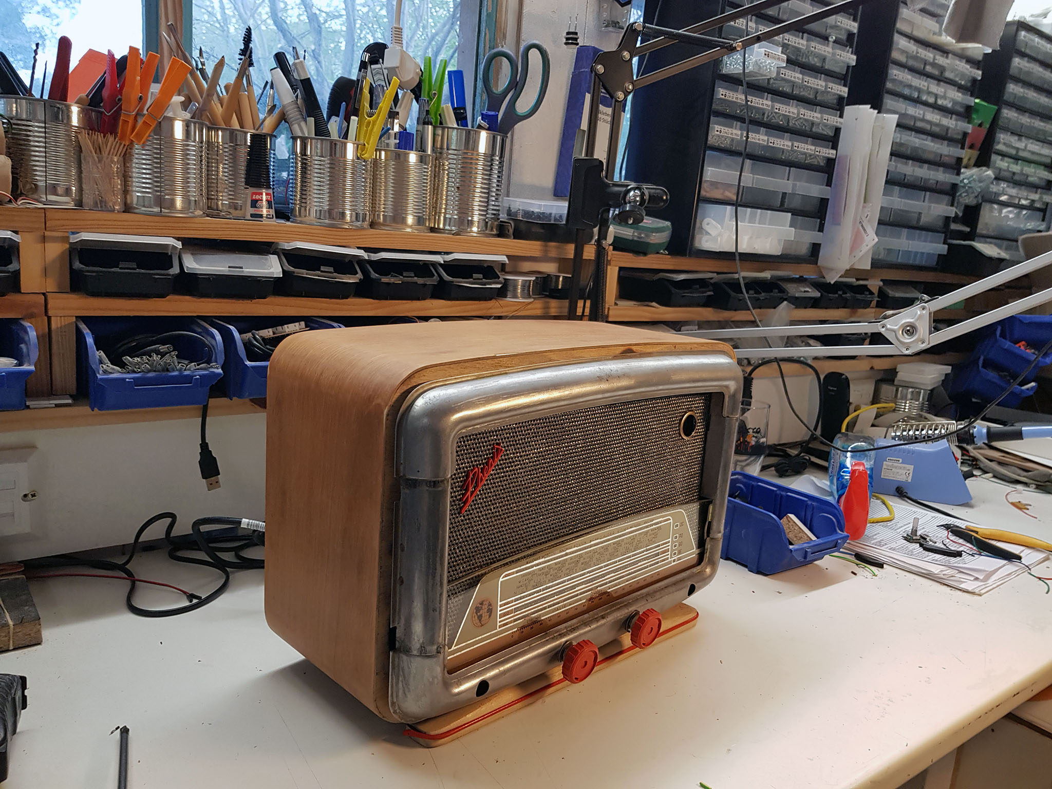
But: transformer un vieux poste radio a lampes HS des années 60/70 récupéré en vide grenier en poste mp3 avec un raspberry Pi.
Au niveau Matériel :
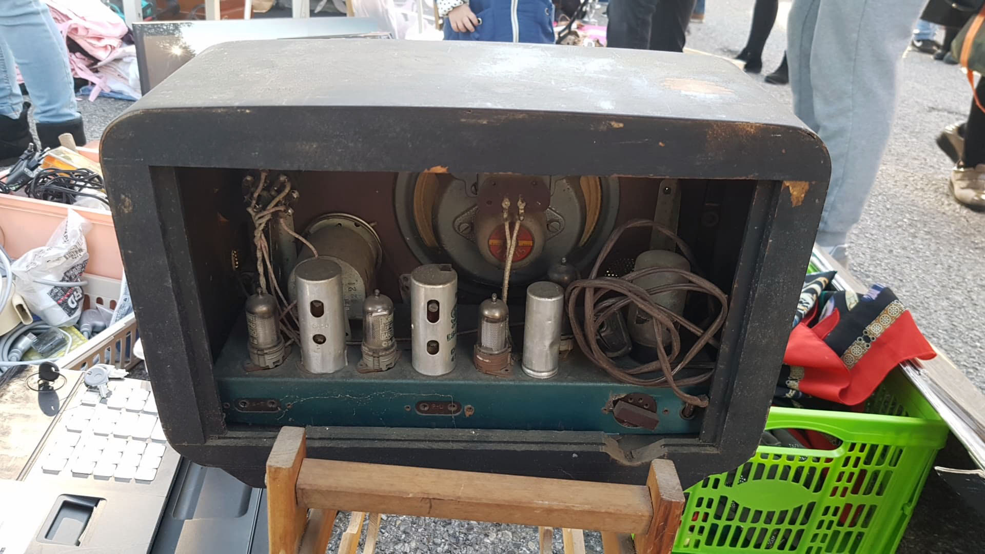
– un vieux poste radio a lampes HS des années 60/70
– un Raspberry Pi
– un ampli 2.1 20W
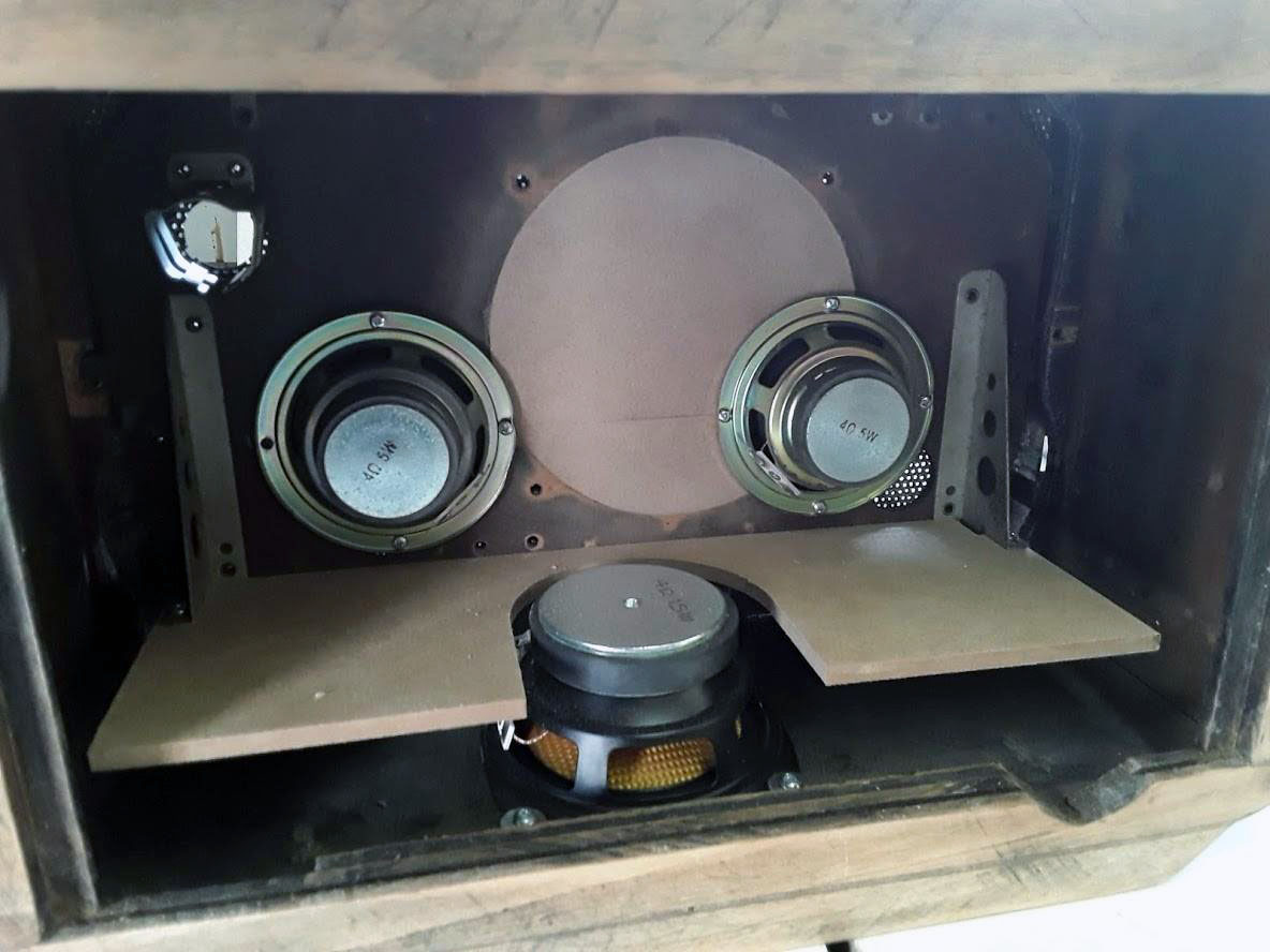
– 3 HP 5W
– un Afficheur 128×128 pixels
– deux encodeurs rotatifs
– un disque dur SSD avec adaptateur USB
– horloge RTC en I2C
– bande de led RGB
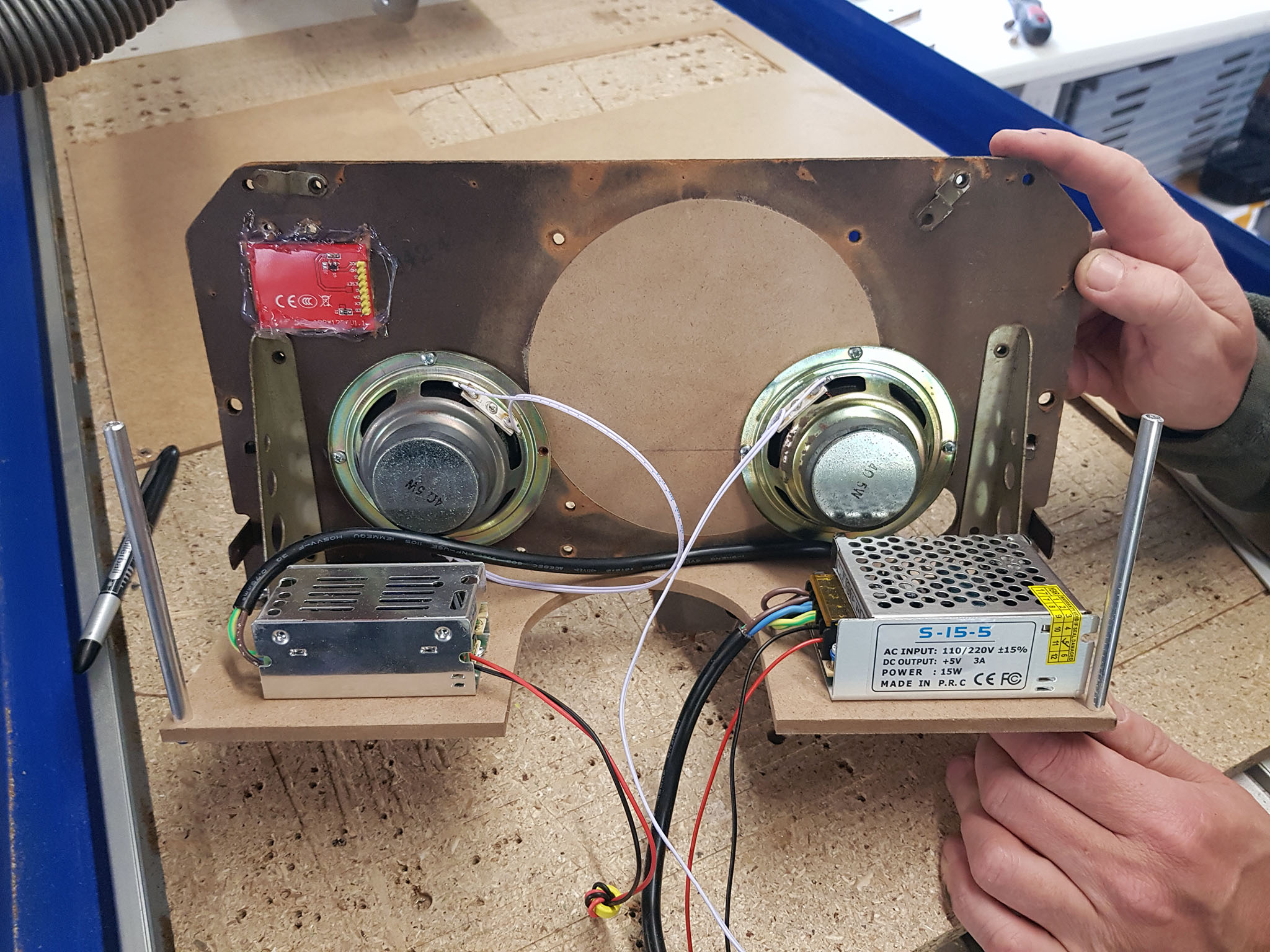
– deux alimentations 220v/5V ( une pour la partie Audio , l’autre pour la partie « numérique » 5A) et conneteur alimentation et interrupteur M/A
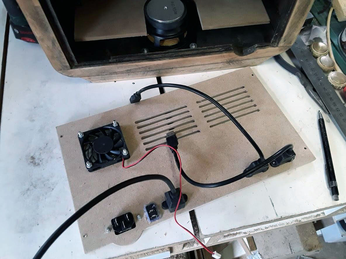
– un ventilateur 5V avec grille
– un disque dur SSD ( dans mon cas un 120Go)
ou trouvez les divers éléments :
1 x Raspberry Pi
2 x 3-inch-Full-Range-Speaker-4ohm-5W
1 x 4-Pouces Haut-Parleur-4-Ohm-15-W graves
1x Ampli 2.1 20W 5V
2 x Encodeur rotatif
1 x Horloge I2C
2 x alimentation 220v -5v 3A
2 x câble USB
1 x câble réseau
1 x ventilateur 5v+1 x grille 60mm
1 x interrupteur + 1 x connecteur alimentation
Au niveau logiciel :
– Raspbian lite dernière version
– daemon mpd
– python3
– scripts divers ( gestion des encodeurs rotatif en émulation clavier UP,DOWN,LEFT,RIGHT,ENTER,PLAUY/PAUSE).
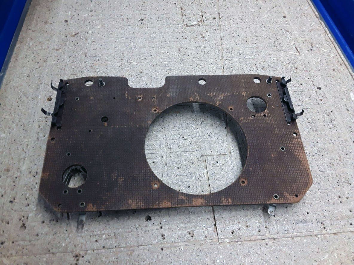
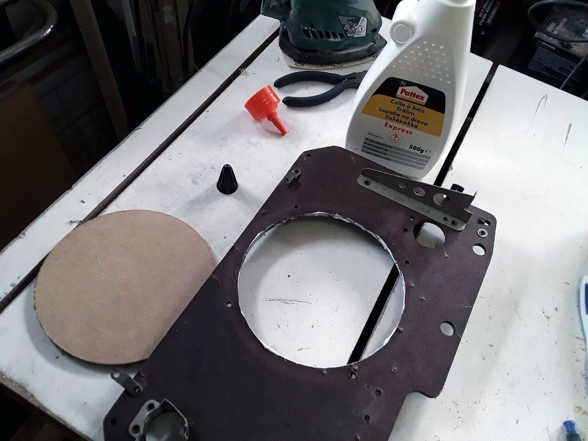
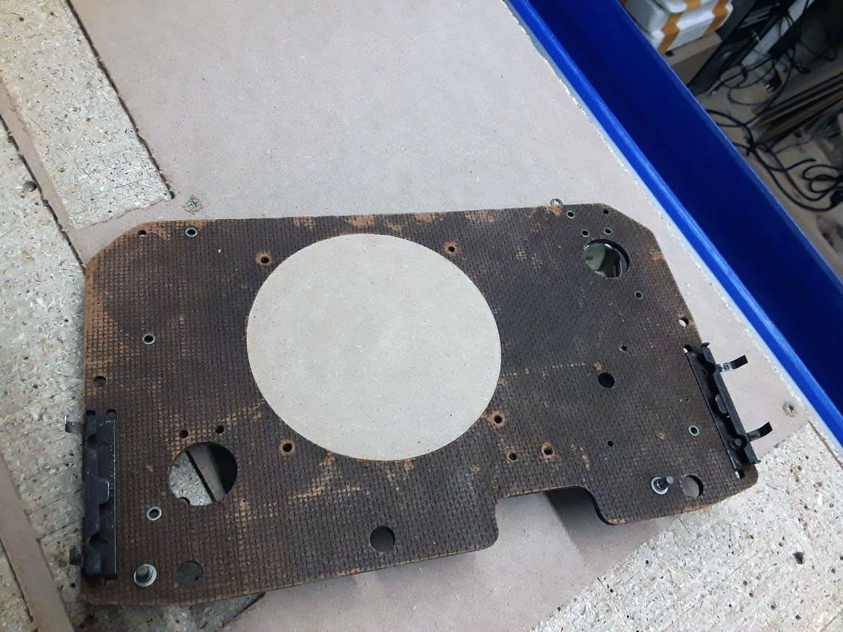
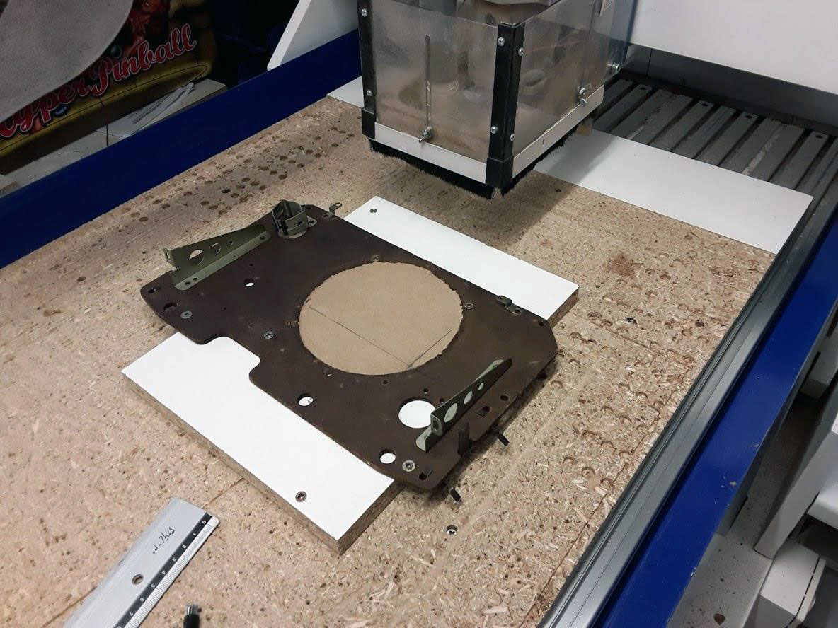
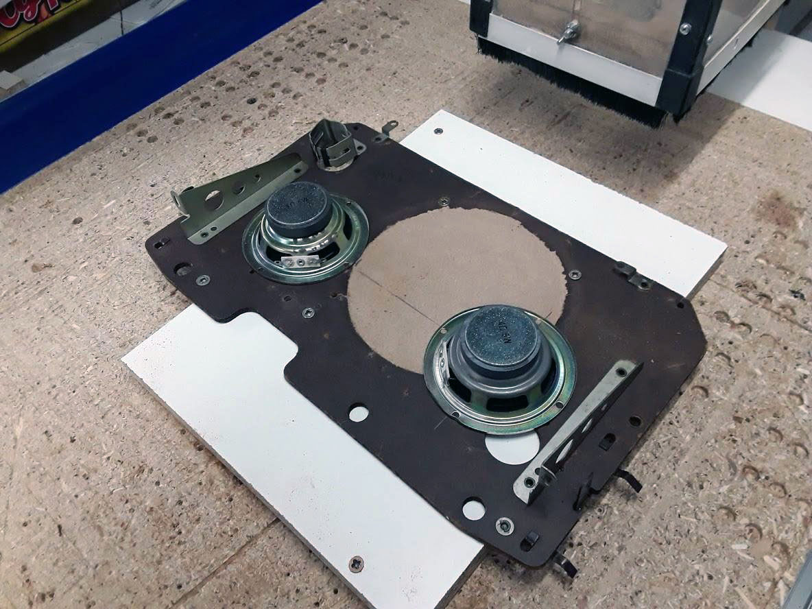
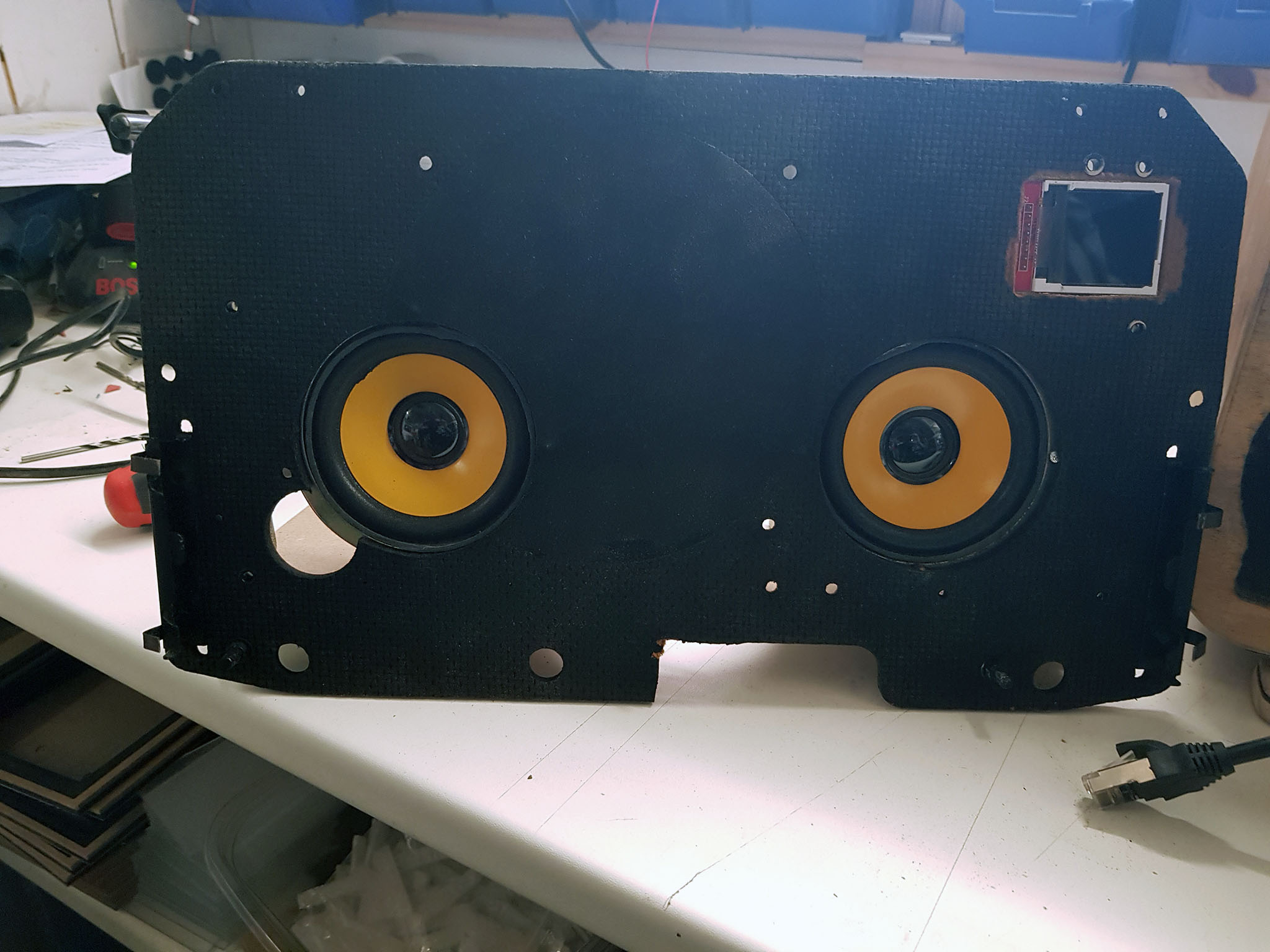
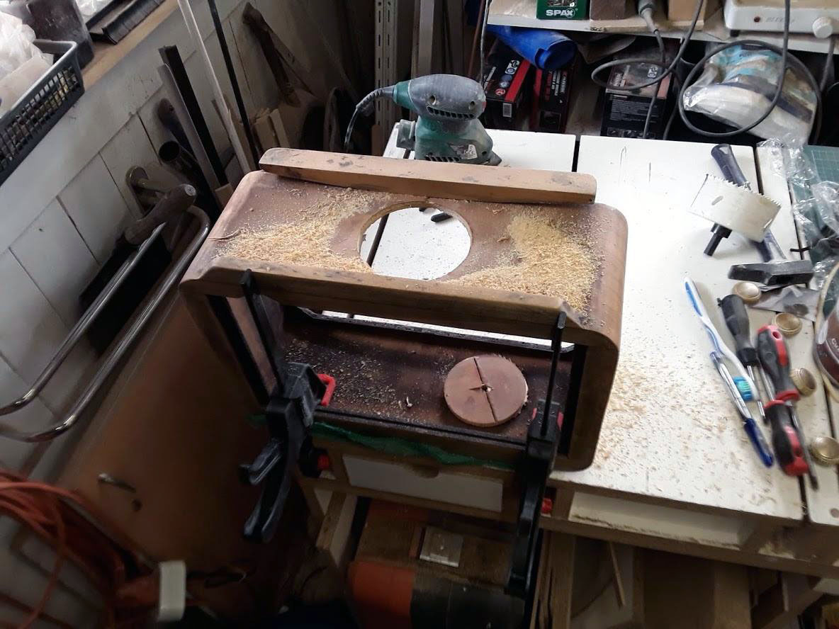
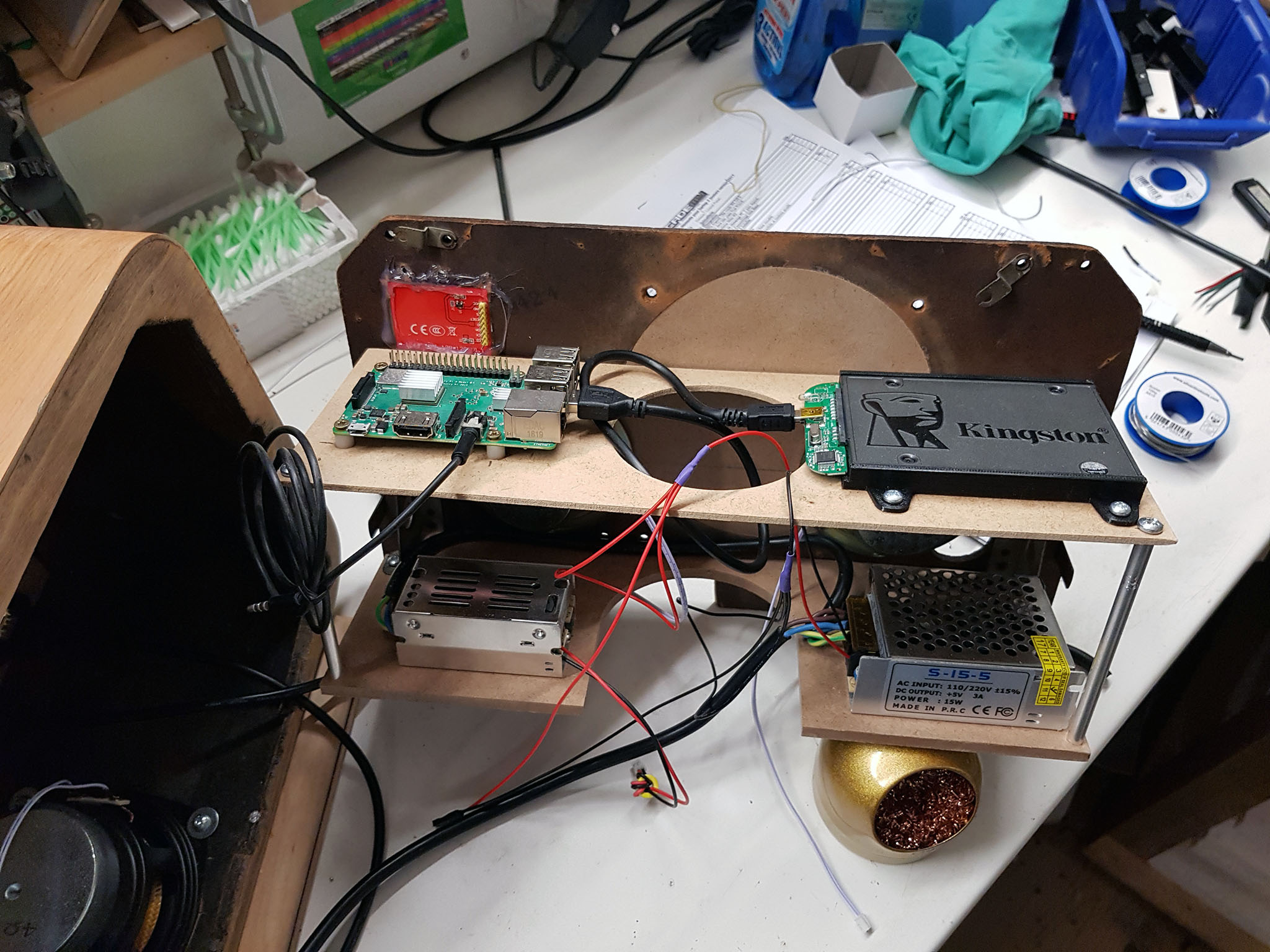
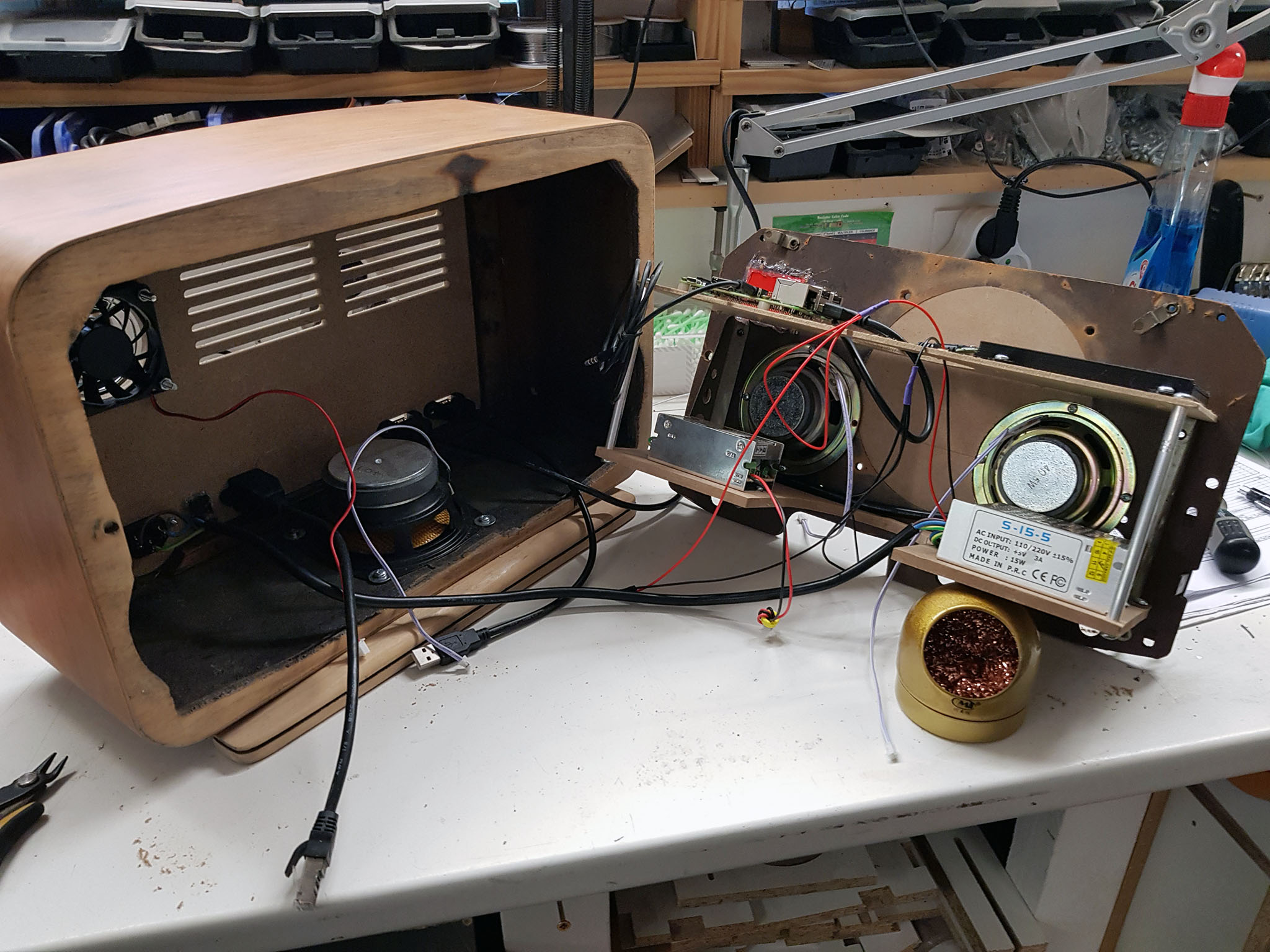
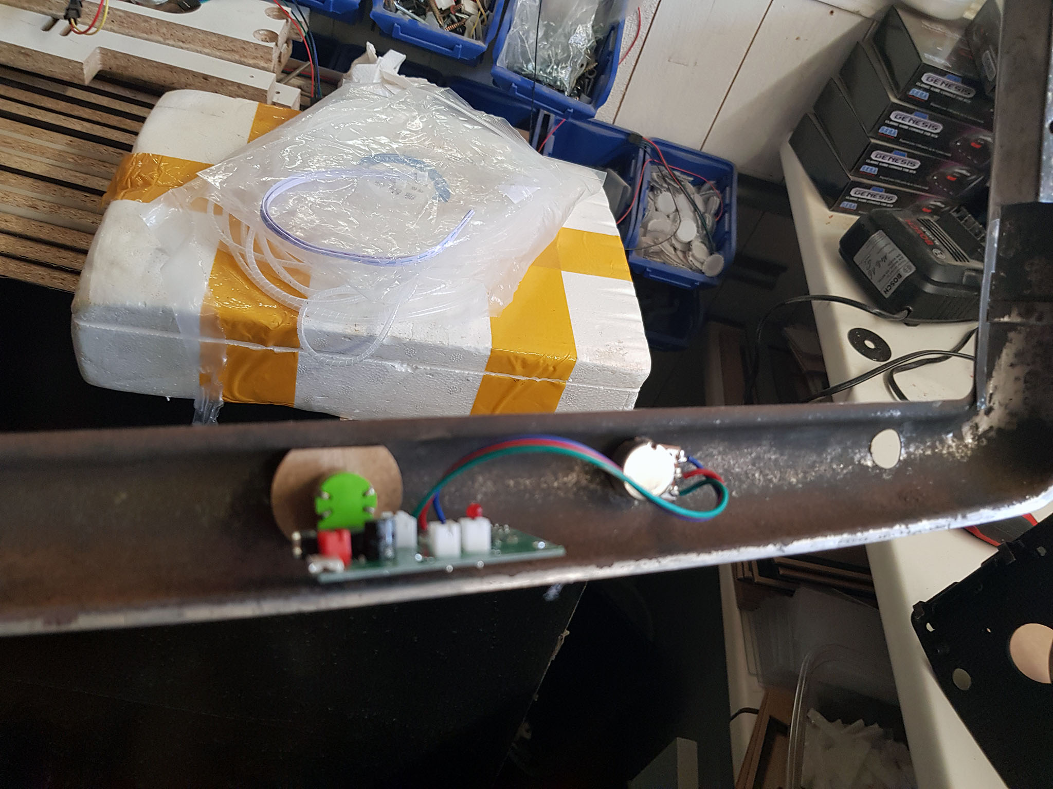
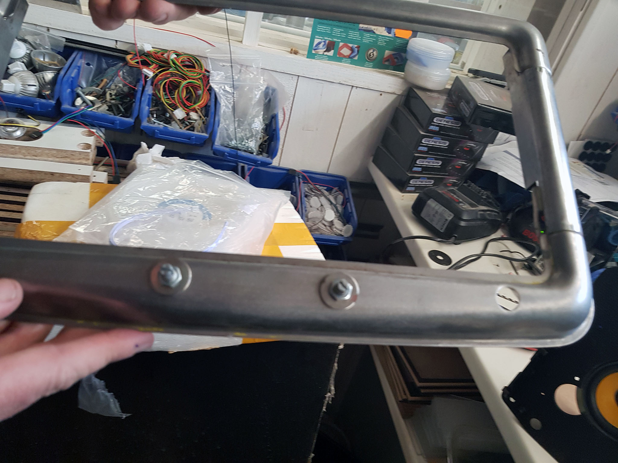
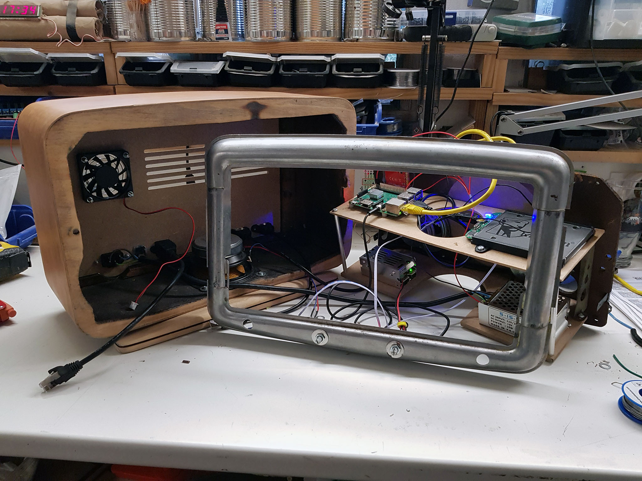
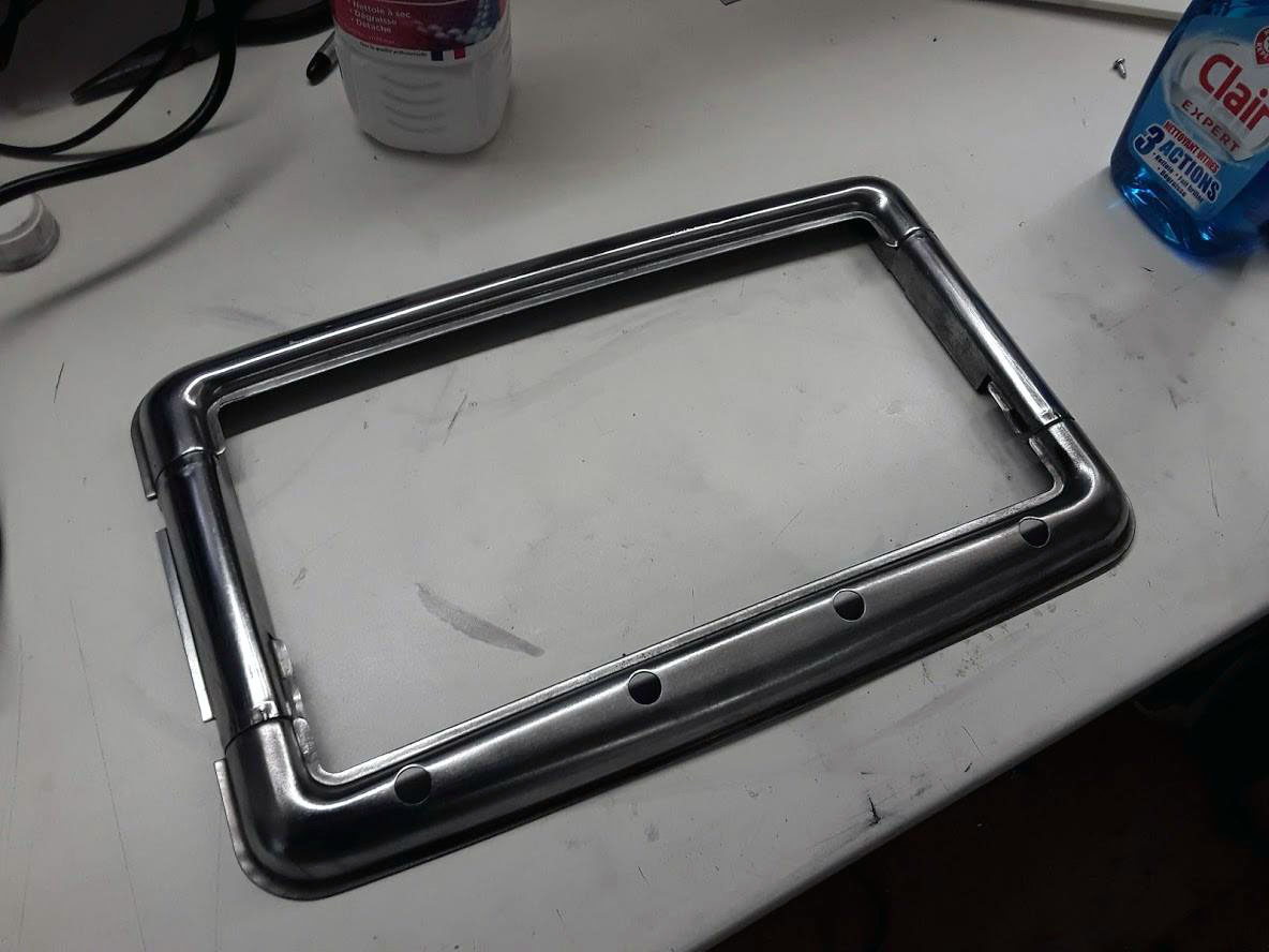
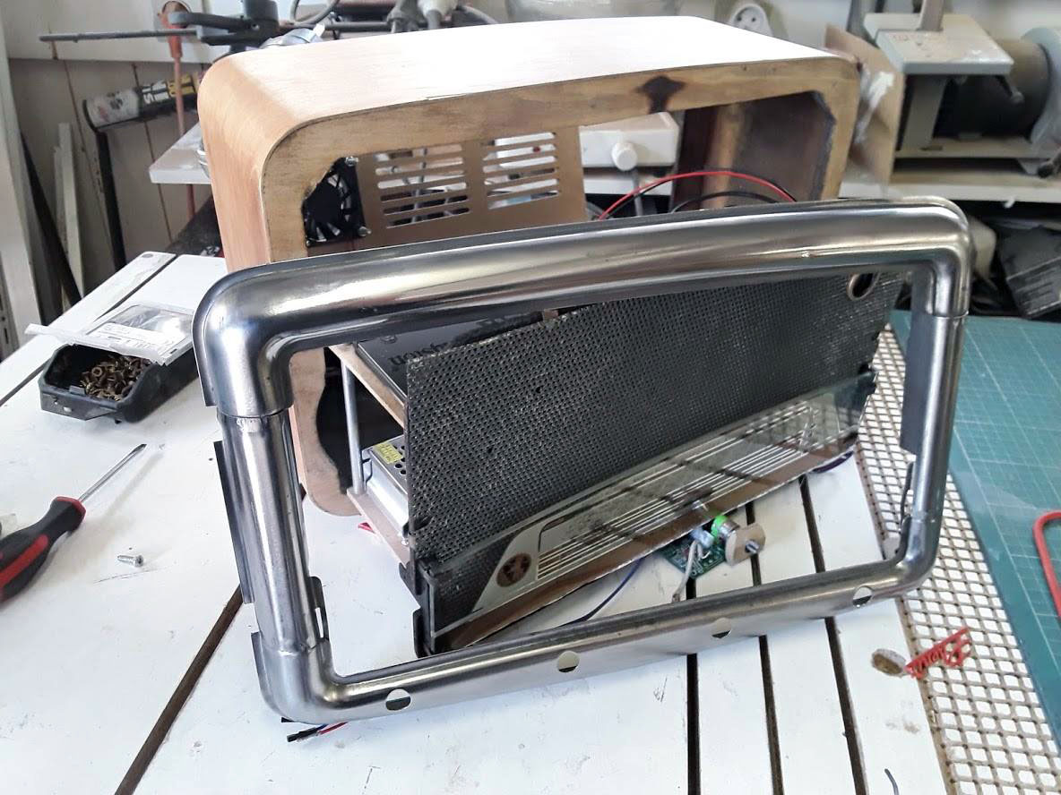
Photos de la transformation :
 |
 |
 |
 |
 |
 |
 |
 |
 |
 |
 |
 |
 |
 |
 |
 |
 |
 |
 |
 |
 |
 |
 |
 |
 |
 |
 |
 |
 |
 |
 |
 |
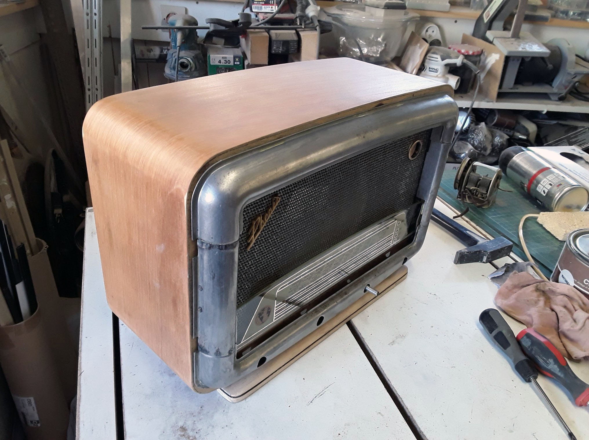
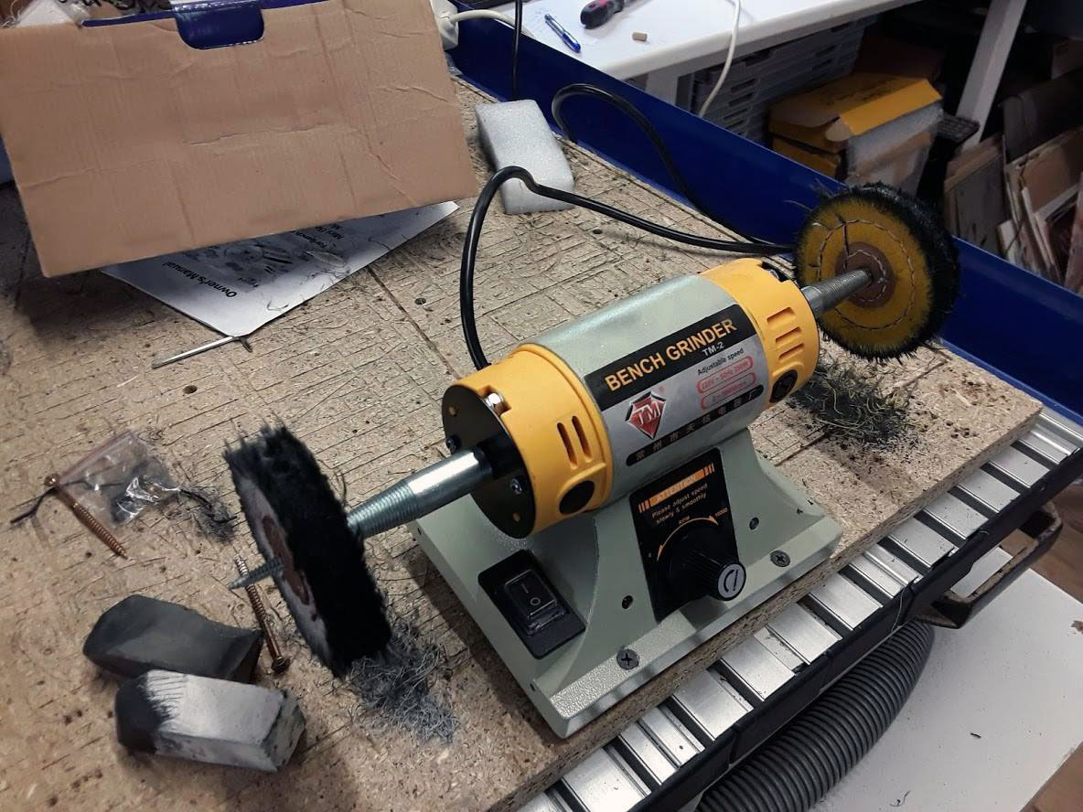
bon j’avoue en étant électronicien / informaticien , je déteste la partie « mécanique » ( boitier et autre ) , c’est donc mon beau-frère qui s’occupe de cette partie en plus ayant son Fablab perso il a tous les outils nécessaire
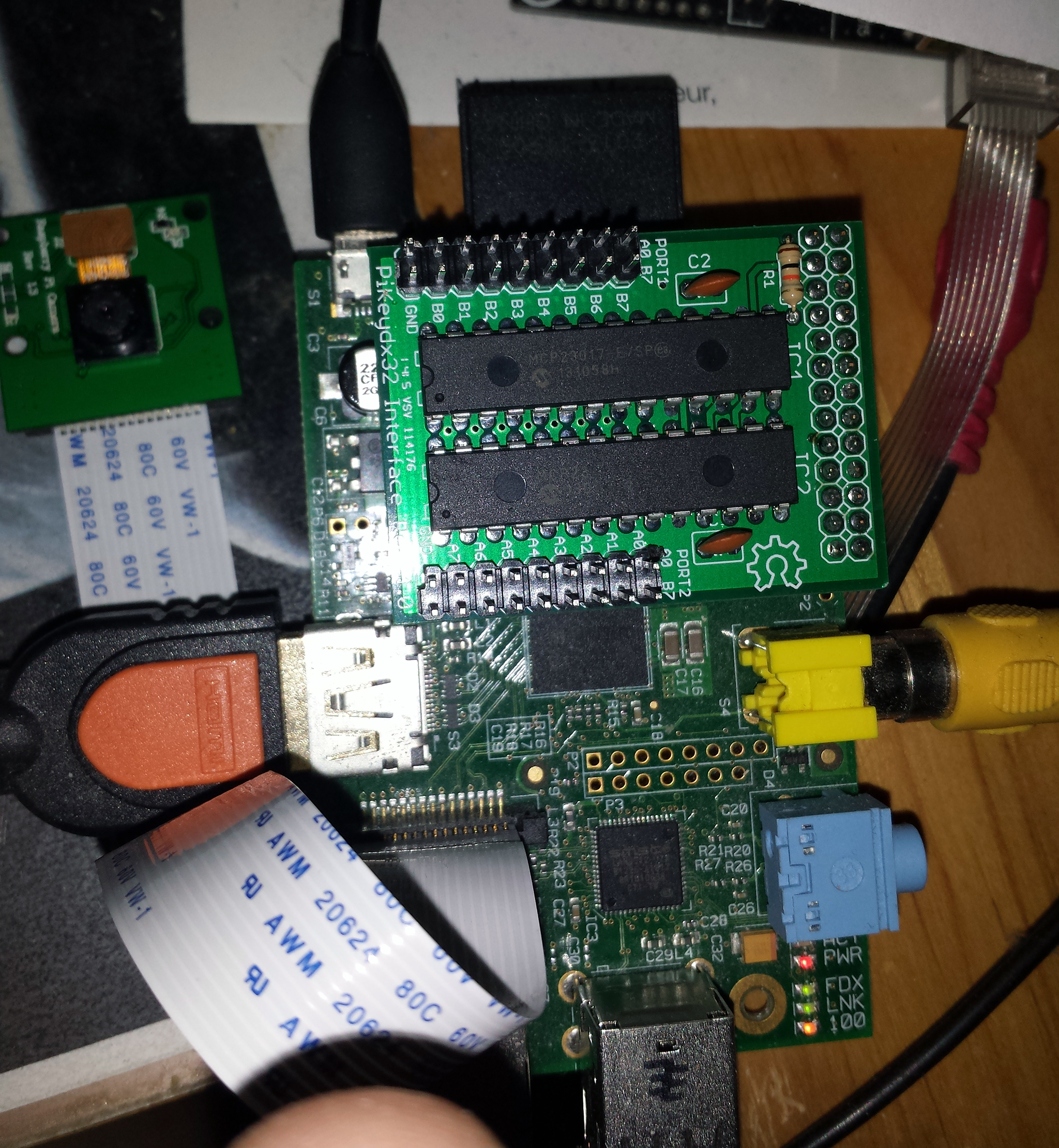
pour remplacer la lampe de « l’Œil magique » un afficheur 1.44” SPI de 128×128 pixels qui permettra d’afficher divers menu et aussi la pochette de la piste en cours a base de st7735 / ili9163

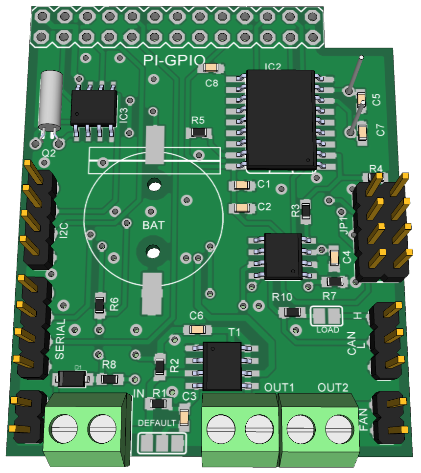
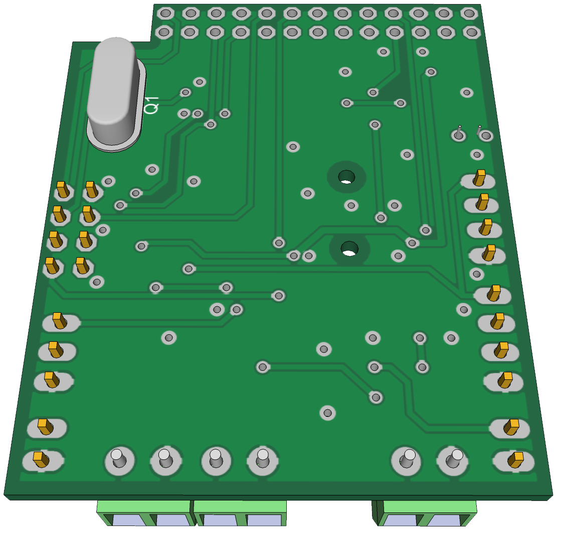
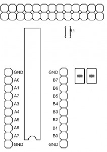
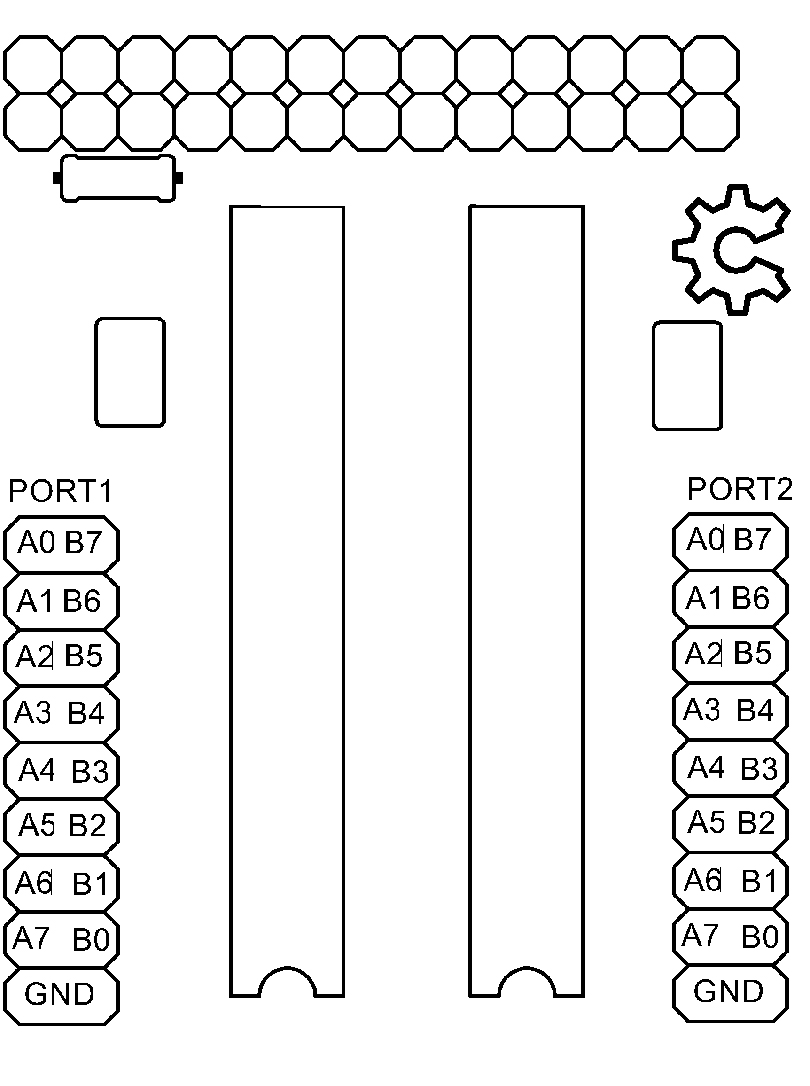
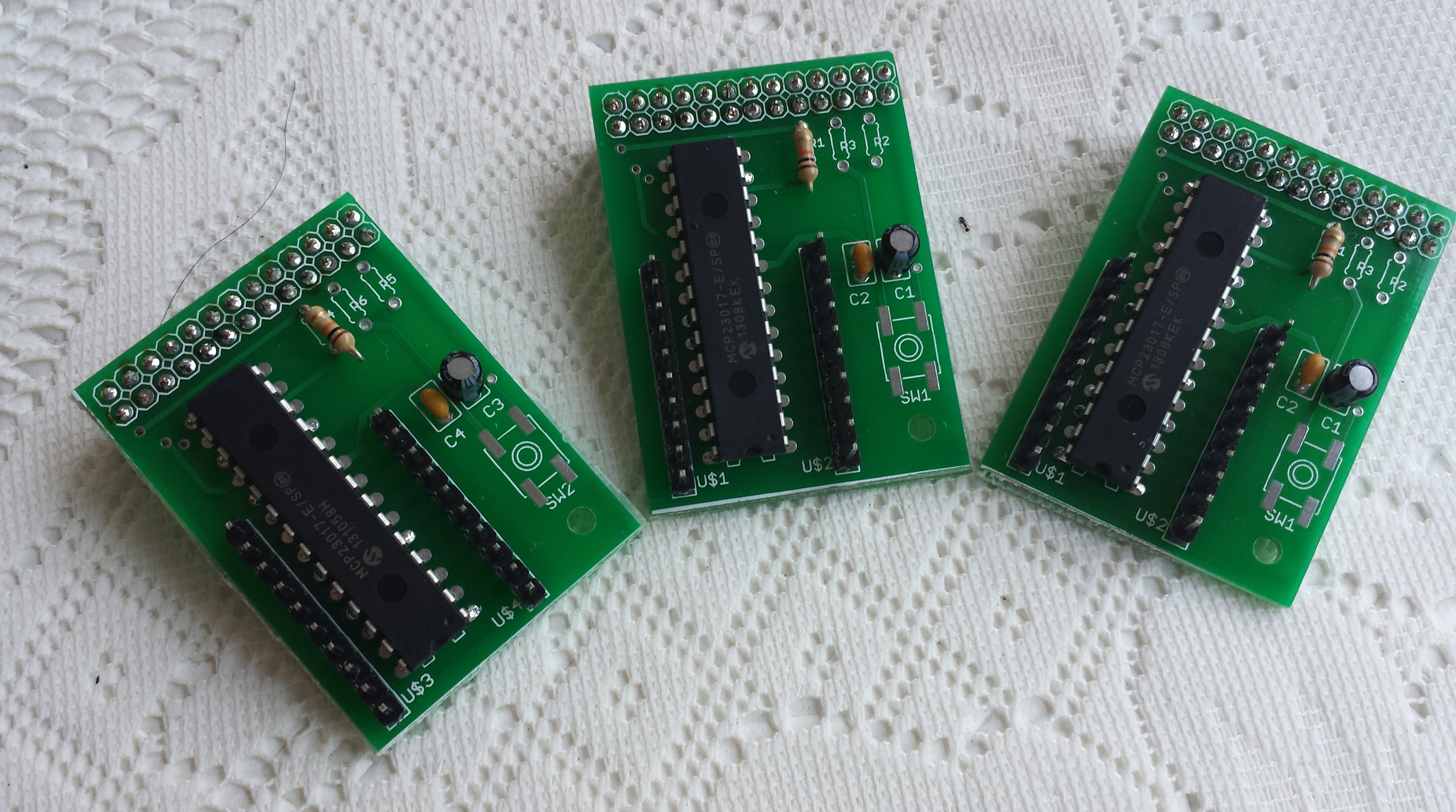
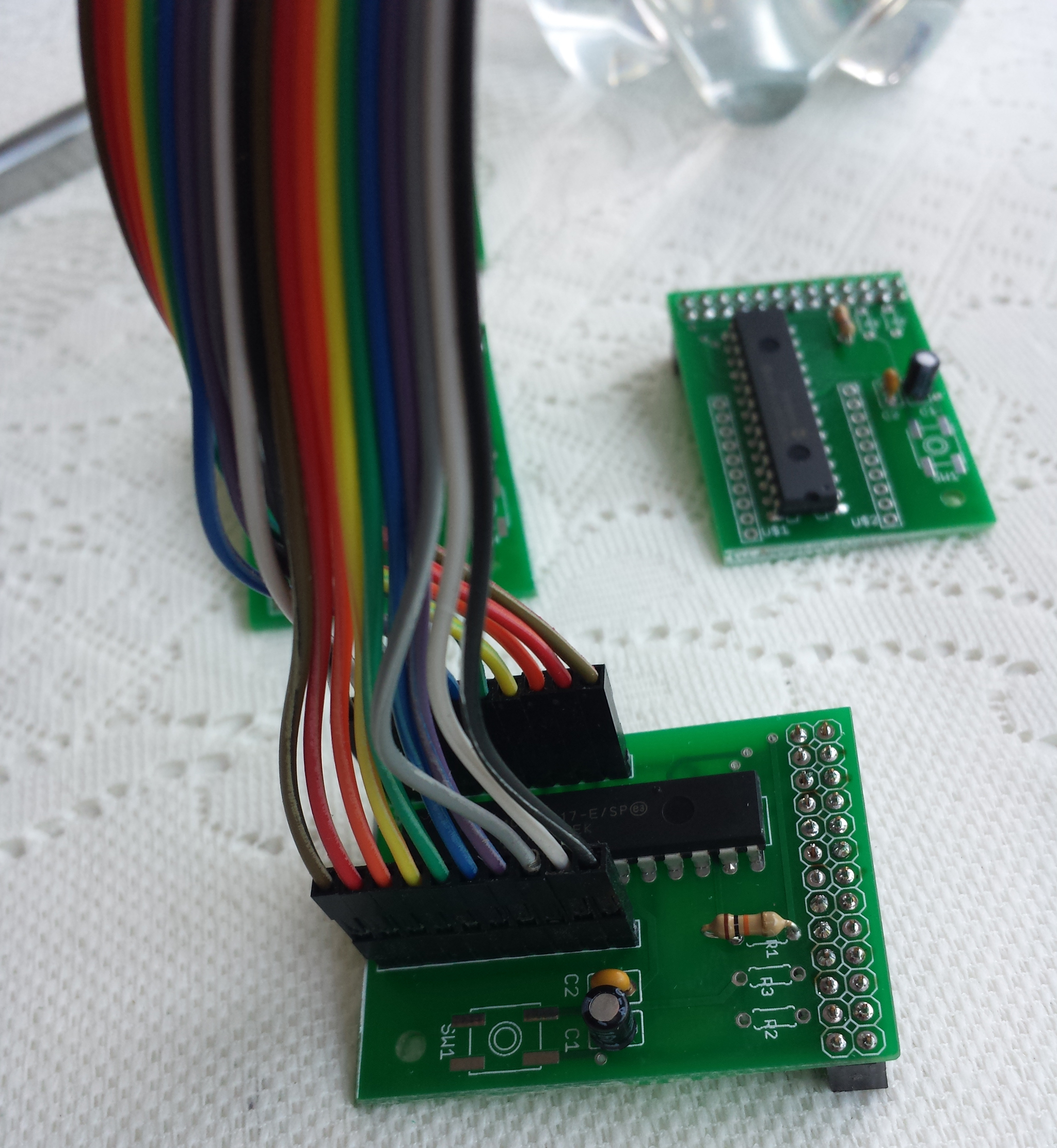
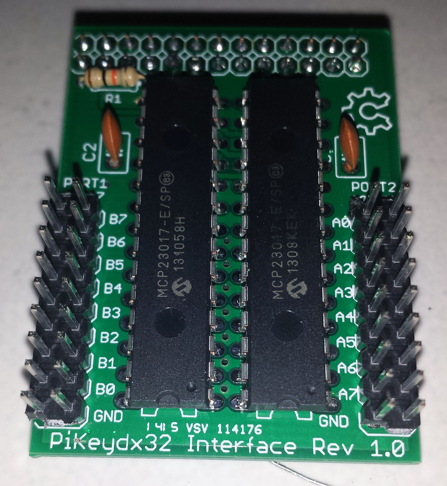
câblage des GPIO ( provisoire)
| Name | Usage | Board | Usage | Name |
| 3.3V | RTC.VCC | 01 | | 02 | LED.VCC | 5V |
| GPIO02 | RTC.SDA | 03 | | 04 | LCD.VCC | 5V |
| GPIO03 | RTC.SCL | 05 | | 06 | GND | |
| GPIO04 | 07 | | 08 | U_TXD | GPIO14 | |
| GND | RTC.GND | 09 | | 10 | U_RXD | GPIO15 |
| GPIO17 | ENC1.B | 11 | | 12 | SPI1_CE0 | GPIO18 |
| GPIO27 | ENC1.A | 13 | | 14 | LCD.GND | GND |
| GPIO22 | ENC1.SW | 15 | | 16 | LCD.LED | GPIO23 |
| 3.3V | 17 | | 18 | LCD.A0 | GPIO24 | |
| GPIO10 | LCD.SDA | 19 | | 20 | GND | |
| GPIO09 | 21 | | 22 | LCD.RST | GPIO25 | |
| GPIO11 | LCD.SCK | 23 | | 24 | LCD.CS | GPIO08 |
| GND | ENC1.GND | 25 | | 26 | GPIO07 | |
| ID_SD0 | * | 27 | | 28 | * | ID_SC1 |
| GPIO05 | ENC2.A | 29 | | 30 | FAN.GND | GND |
| GPIO06 | ENC2.B | 31 | | 32 | FAN.PWM | GPIO12 |
| GPIO13 | ENC2.SW | 33 | | 34 | LED.GND | GND |
| GPIO19 | SPI1_MISO | 35 | | 36 | GPIO16 | |
| GPIO26 | 37 | | 38 | LED.DI | GPIO20 | |
| GND | ENC2.GND | 39 | | 40 | SPI1_SCLK | GPIO21 |
installation logicielle , j’ai décidé de me passer de carte SD sur le Raspberry et booter directement sur le SSD ( voir article frambroise 314 )
j’ai fait 3 partions sur le hdd (/dev/sda1 vfat 100M , /dev/sda2 ext4 8Go , /dev/sda3 ext4 le reste du disque pour stockage des fichiers audios )
mon /etc/fstab
proc            /proc           proc    defaults          0       0
PARTUUID=0c9f0562-01  /boot           vfat    defaults          0       2
PARTUUID=0c9f0562-02  /               ext4    defaults,noatime  0       1
PARTUUID=0c9f0562-03  /var/lib/mpd    ext4    defaults,noatime  0       1
une fois raspbian lite installé et le raspberry pi en route on commence a installer les paquets nécessaire :
sudo apt install python3-pygame python-pygame python-spidev python3-spidev
sudo apt install mpd python-pip python3-pip
sudo apt install evtest telnet samba lame flac faad vorbis-tools
sudo apt install mc alsa-utils libmpdclient-dev cython

pip install python-uinput
pip install python-mpd2
pip3 install python-mpd2
fichier a créer / modifier
- /etc/modprobe.d/fbtft.conf
options fbtft_device name=fb_ili9163 gpios=reset:25,dc:24,led:23 speed=40000000 rotate=90 bgr=1 custom=1 fps=60
- /etc/modules-load.d/fbtft.conf
spi-bcm2835
fbtft_device
- /etc/modules-load.d/RotaryKey.conf
uinput
logiciels a installer /compiler , je met tous dans /opt/scripts
cd /opt
mkdir scripts
cd /opt/scripts
- Automatic library-wide shuffle for mpd ( gestion playlist aléatoire )
git clone https://github.com/joshkunz/ashuffle.git
cd ashuffle/
make
sudo make install
- mpd Album Art
git clone https://github.com/jameh/mpd-album-art.git
cd mpd-album-art
sudo python3 setup.py install
- gestion du clavier virtuel depuis les 2 encodeurs rotatifs
- /opt/scripts/RadioKey.py ( script pour gerer le « clavier ») pour l’instant un seul encodeur géré UP,DOWN,ENTER
#!/usr/bin/env python import RPi.GPIO as GPIO import uinput from time import sleep # version PCB pin_a1 = 37 #GPIO 13 pin_b1 = 35 #GPIO 19 pin_sw1= 33 #GPIO 26 pin_a2 = 36 #GPIO 16 pin_b2 = 38 #GPIO 20 pin_sw2= 40 #GPIO 21 GPIO.setmode(GPIO.BOARD) GPIO.setup(pin_a1, GPIO.IN, pull_up_down=GPIO.PUD_UP) GPIO.setup(pin_b1, GPIO.IN, pull_up_down=GPIO.PUD_UP) GPIO.setup(pin_sw1, GPIO.IN, pull_up_down=GPIO.PUD_UP) GPIO.setup(pin_a2, GPIO.IN, pull_up_down=GPIO.PUD_UP) GPIO.setup(pin_b2, GPIO.IN, pull_up_down=GPIO.PUD_UP) GPIO.setup(pin_sw2, GPIO.IN, pull_up_down=GPIO.PUD_UP) device = uinput.Device([uinput.KEY_UP, uinput.KEY_DOWN,uinput.KEY_ENTER,uinput.KEY_PLAYPAUSE,uinput.KEY_LEFT,uinput.KEY_RIGHT]) seq_a1 = seq_b1 = seq_sw1=0 seq_a2 = seq_b2 = seq_sw2=0 def on_Sw(pin): sw = GPIO.input(pin_sw2) if sw == 0: device.emit_click(uinput.KEY_ENTER) sw = GPIO.input(pin_sw1) if sw == 0: device.emit_click(uinput.KEY_PLAYPAUSE) def on_edge1(pin): global seq_a1, seq_b1 a1 = GPIO.input(pin_a1) b1 = GPIO.input(pin_b1) seq_a1 = ((seq_a1 << 1) | a1) & 0b1111 seq_b1 = ((seq_b1 << 1) | b1) & 0b1111 if seq_a1 == 0b0011 and seq_b1 == 0b1001: device.emit_click(uinput.KEY_UP) elif seq_a1 == 0b1001 and seq_b1 == 0b0011: device.emit_click(uinput.KEY_DOWN) def on_edge2(pin): global seq_a2, seq_b2 a2 = GPIO.input(pin_a2) b2 = GPIO.input(pin_b2) seq_a2 = ((seq_a2 << 1) | a2) & 0b1111 seq_b2 = ((seq_b2 << 1) | b2) & 0b1111 if seq_a2 == 0b0011 and seq_b2 == 0b1001: device.emit_click(uinput.KEY_LEFT) elif seq_a2 == 0b1001 and seq_b2 == 0b0011: device.emit_click(uinput.KEY_RIGHT) GPIO.add_event_detect(pin_a1, GPIO.BOTH, callback=on_edge1) GPIO.add_event_detect(pin_b1, GPIO.BOTH, callback=on_edge1) GPIO.add_event_detect(pin_a2, GPIO.BOTH, callback=on_edge2) GPIO.add_event_detect(pin_b2, GPIO.BOTH, callback=on_edge2) GPIO.add_event_detect(pin_sw1, GPIO.BOTH, callback=on_Sw) GPIO.add_event_detect(pin_sw2, GPIO.BOTH, callback=on_Sw) try: while True: sleep(300) except KeyboardInterrupt: GPIO.cleanup() - Service RadioKey ( deamon clavier ) : /etc/systemd/system/RadioKey.service
[Unit]
Description=Python start + foreground + keyboard input.
Requires=multi-user.target
After=multi-user.target rc-local.service
AllowIsolate=yes

[Service]
Type=simple
ExecStart=/usr/bin/python /opt/scripts/RadioKey.py

[Install]
WantedBy=multi-user.target
- activation du service
systemctl daemon-reload
service RadioKey start
- test du clavier virtuel

- /opt/scripts/RadioKey.py ( script pour gerer le « clavier ») pour l’instant un seul encodeur géré UP,DOWN,ENTER
- script au démarrage qui affiche l’IP du pi sur l’afficheur 128×128 ( /opt/scripts/ip.py) pendant 10 secondes
#!/usr/bin/env python import os import sys import time import pygame import socket def get_ip_address(): ip_address = ''; s = socket.socket(socket.AF_INET, socket.SOCK_DGRAM) try: s.connect(("8.8.8.8",80)) ip_address = s.getsockname()[0] s.close() return ip_address except socket.error, msg: return "0.0.0.0" os.environ["SDL_FBDEV"] = "/dev/fb1" os.environ['SDL_VIDEODRIVER']="fbcon" mapMask= pygame.image.load("/home/pi/mask.png") def displaytext(text,size,line,color,clearscreen): if clearscreen: screen.fill((255,0,0)) font = pygame.font.Font(None,size) text = font.render(text,0,color) rotated = pygame.transform.rotate(text,0) textpos = rotated.get_rect() textpos.centerx = 64 textpos.centery = 64 screen.blit(rotated,textpos) def main(): global screen pygame.init() pygame.mouse.set_visible(0) size = width,height = 128,128 screen = pygame.display.set_mode(size) str=get_ip_address() displaytext( str,26,1,(255,255,255),True) screen.blit(mapMask, (0,0)) pygame.display.flip() time.sleep(10) pygame.quit() exit() if __name__ == '__main__': main() - interface web pour playlist (https://www.ympd.org/ )
cd /opt/scripts
wget https://www.ympd.org/downloads/ympd-1.2.3-armhf.tar.bz2
tar -xvf ympd-1.2.3-armhf.tar.bz2
sudo ./ympd --webport 80
- partage dossier réseau ( /etc/samba/smb.conf )
#======================= Global Settings =======================
[global]
   workgroup = WORKGROUP
   dns proxy = no
   log file = /var/log/samba/log.%m
   max log size = 1000
   syslog = 0
   panic action = /usr/share/samba/panic-action %d
   server role = standalone server
   passdb backend = tdbsam
   obey pam restrictions = yes
   unix password sync = yes
   passwd program = /usr/bin/passwd %u
   passwd chat = *Enter\snew\s*\spassword:* %n\n *Retype\snew\s*\spassword:* %n\n *password\supdated\ssuccessfully* .
   pam password change = yes
   map to guest = bad user
   usershare allow guests = yes

#======================= Share Definitions =======================
[home]
   browseable = yes
   create mask = 0700
   directory mask = 0700
   guest ok = yes
   path = /home/pi
   force user =  pi
   force group = pi
   read only = No

[scripts]
   browseable = yes
   create mask = 0700
   directory mask = 0700
   guest ok = yes
   path = /opt/scripts
   force user =  pi
   force group = pi
   read only = No

[Media]
   browseable = yes
   create mask = 0700
   directory mask = 0700
   guest ok = yes
   path = /var/lib/mpd/
   force user =  mpd
   force group = audio
   read only = No
- gestion de led RGB ws2812 , pour cela on va activer le 2eme port SPI ( raspberry pi 3
dans /boot/config.txt ajouter/modifierspidev.bufsiz=32768 dtoverlay=spi1-1cs
ensuite on vas ajouter py-spidev et ws2812-spi
sudo apt install python-spidev python3-spidev

cd /opt/scripts
git clone https://github.com/doceme/py-spidev.git
cd py-spidev
make
make install

cd /opt/scripts
git clone https://github.com/joosteto/ws2812-spi.git
cd ws2812-spi
en fonction du Pi utilisé il faut modifier le fichier ws2812.py , dans def write2812_numpy4(spi,data): commenter toutes les lignes spi.xfer et de-commenter celle ci : spi.xfer(tx.tolist(), int(4/.55e-6))
ensuitesudo python setup.py install
on vas tester le bandeau :
cd /opt/scripts
nano loop.py
dans mon cas il y auras 20 led RGB ws2812 donc :
import spidev
import ws2812
import time
import getopt

def test_loop(spi, nLED=8, intensity=20):
    stepTime=0.1
    iStep=0
    while True:
        d=[[0,0,0]]*nLED
        d[iStep%nLED]=[intensity]*3
        ws2812.write2812(spi, d)
        iStep=(iStep+1)%nLED
        time.sleep(stepTime)

if __name__=="__main__":
    spi = spidev.SpiDev()
    spi.open(1,0)

    test_loop(spi, nLED=20)
puis python loop.py
- (en cours de dev …….) gestion du bandeau lumineux en fonction de la musique ( basé sur https://github.com/nvbn/soundlights)
cd /opt/scripts
git clone https://github.com/nvbn/soundlights.git
./autogen.sh
./configure
make
sudo make install
création du fichier de config : nano /opt/scripts/config.led :
[general]
mode = normal
framerate = 60
bars = 20

[input]
method = fifo
source = /tmp/mpd.fifo

[output]
method =raw
channels = stereo
bit_format = 8bit

[eq]
1=2
2=2
3=1
4=1
5=0.5
fichier /opt/scripts/soundlights.py
import sys
import time
import spidev
import ws2812

COLORS_COUNT = 255
nLED=20
spi = spidev.SpiDev()
spi.open(1,0)
d=[(0,0,0)]*nLED
ws2812.write2812(spi, d)

def _get_spaced_colors(n):
    max_value = 4144959
    interval = int(max_value / n)
    colors = [hex(i)[2:].zfill(6) for i in range(0, max_value, interval)]
    return [ (int(i[:2], 16), int(i[2:4], 16), int(i[4:], 16)) for i in colors]

def _handle_stdin(colors,d):
    while True:
        try:
            ws2812.write2812(spi, colors)
        except Exception as e:
            print e

if __name__ == '__main__':
    _handle_stdin(_get_spaced_colors(COLORS_COUNT),d)
puis on teste en lançant :
cava -p config.led | python soundlights.py
- version alpha partie affichage covertArt piste en cours et passer piste suivante/précédente
#!/usr/bin/python3
# -*- coding: utf-8 -*-
import pygame
import math
import os
import time
import sys
import mpd_album_art
from mpd import (MPDClient, CommandError)

# ecran TFT en /dev/fb1
os.putenv("SDL_VIDEODRIVER", "fbcon")
os.environ["SDL_FBDEV"] = "/dev/fb1"

# pour daemon mpd
HOST = 'localhost'
PORT = '6600'
CON_ID = {'host':HOST, 'port':PORT}
def mpdConnect(client, con_id):
    try:
        client.connect(**con_id)
    except:
        return False
    return True

#maj covertArt
def update_folder(client,pygame,window):
    status = client.status()
    now_playing = client.currentsong()
    print ('file    : ' + now_playing.get('file'))
# chercher coverart et lien vers "/home/pi/.covers/current"
    grabber = mpd_album_art.Grabber(
        save_dir="/home/pi/.covers",
        library_dir="/var/lib/mpd/music"
        )
    grabber.get_local_art(now_playing)
# maj affichage
    mapImg = pygame.image.load("/home/pi/.covers/current")
    mapImg = pygame.transform.scale(mapImg, (128, 128))
    mapMask= pygame.image.load("/home/pi/mask.png") # masque pour faire la forme de "l’œil magique"
    window.blit(mapImg, (0,0)) #<<will not blit
    window.blit(mapMask, (0,0))
    pygame.display.update() # solution: you forgot this...

def main():
# on se connecte au daemon mpd
    client = MPDClient()
    if mpdConnect(client, CON_ID):
        print('Got connected!')
    else:
        print('fail to connect MPD server.')
        sys.exit(1)
    elapsed=0.00
# init pygame /  afficheur
    pygame.display.init()
    pygame.mouse.set_visible(0)
    window = pygame.display.set_mode((128, 128))
    pygame.event.clear()
    window.fill((0,0,0))
# affiche coverArt piste en cours
    update_folder(client,pygame,window)
    while True:
        status = client.status()
#  test si temp_lecture < temp_lecture precedent pour detecter nouvelle piste
        if (elapsed < float(status.get('elapsed', 0))): # non , meme piste rien a faire
            elapsed=float(status.get('elapsed', 0))
        else:                                           # oui , nouvelle piste raz temp_lecture et maj covertArt
            elapsed=float(status.get('elapsed', 0))
#            print ( status.get('elapsed', 0))
            now_playing = client.currentsong()
            update_folder(client,pygame,window)
            #print ('file    : ' + now_playing.get('file'))
        time.sleep(1)

	# check si piste
        event = pygame.event.poll() #wait()
# regarde si evemnent clavier (encodeur rotatif)
        if event.type==pygame.KEYDOWN:
            if event.key==pygame.K_RETURN: # pour l'instant arret soft , a terme play/pause
                pygame.quit()
                client.disconnect()
                sys.exit(0)
            if event.key==pygame.K_UP: # piste suivante
                client.next()
                pygame.event.clear()
		#time.sleep(1)
                elapsed=0
                update_folder(client,pygame,window)
            if event.key==pygame.K_DOWN: # piste precedente
                client.previous()
                pygame.event.clear()
		#time.sleep(1)
                elapsed=0
                update_folder(client,pygame,window)

if __name__ == "__main__":
    main()
pour l’instant partie « mécanique » finis à 90¨% , et partie Electronique / dev finis a 70%
lorsque le soft seras terminé a 100% , je mettrais dispo les sources de tous les fichiers/scripts utilisés
la suite bientôt ……..
Articles qui m’on servis pour développer
https://github.com/petervflocke/rotaryencoder_rpi
https://www.instructables.com/id/PWM-Regulated-Fan-Based-on-CPU-Temperature-for-Ras/
https://www.pihomeserver.fr/2014/03/08/raspberry-pi-home-server-ajouter-une-horloge-rtc-ds1307-sur-le-bus-i2c/
http://blog.gegg.us/2017/01/setting-up-a-gpio-button-keyboard-on-a-raspberry-pi/
https://blog.oddbit.com/2019/01/19/pipower-a-raspberry-pi-ups/https://github.com/joshkunz/ashuffle
https://github.com/joosteto/ws2812-spi
https://github.com/nvbn/soundlights